battery module

A battery module, battery technology, applied in secondary batteries, battery/battery traction, circuits, etc., can solve problems such as high energy overhead, adverse effects, easy damage, etc., and achieve high efficiency, rapid cooling, and good heat exchange. Effect

Inactive Publication Date: 2011-12-28
ROBERT BOSCH GMBH
View PDF5 Cites 21 Cited by
  • Summary
  • Abstract
  • Description
  • Claims
  • Application Information

AI Technical Summary

Problems solved by technology

Therefore, a high energy expenditure is required to circulate the temperature-regulated fluid and damage may be prone to occur due to moving mechanical parts of the fluid transfer device
When using such a battery module, the vortex (Drall) of a space station located in outer space may be adversely affected due to the rotating elements in the gas delivery device

Method used


Image

  • battery module
  • battery module
  • battery module

Examples


Embodiment Construction

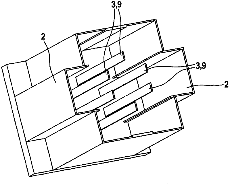
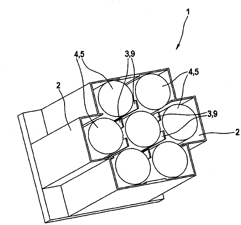
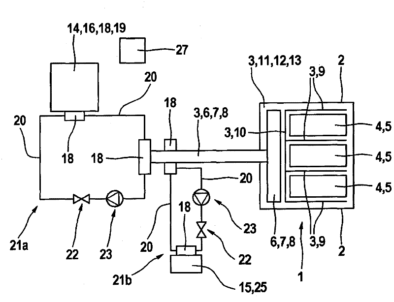
[0027] exist figure 1 A perspective view of a housing 2 of a battery module 1 for accommodating a battery 4 is shown in . exist figure 1 The upper wall of the housing 2 is not shown. The housing 2 consists of plastic and fins 9 made of copper are arranged inside the housing. Between the fins 9 and the housing 2 there is a battery 4 configured as a lithium-ion battery 5 ( figure 2 ). exist figure 1 and 2 Electrical lines for conducting current or supplying current to battery 4 are not shown. The cavities left between the cells 4 in the housing 2 are filled with a heat-conducting liquid 11, such as oil 12, especially silicone oil 13 ( image 3 ). The fins 9 and the silicone oil 13 have a high thermal conductivity, so that the heat dissipated on the surface of the cells 4 can be dissipated well and only small temperature differences occur between the cells 4 of the battery module 1 . The fins 9 and the silicone oil 13 are means 3 for temperature regulation, i.e. cooling...


PUM


Abstract

The invention relates to a battery module with a housing and at least one battery disposed in the housing. At least one element for cooling and / or heating the at least one battery is provided. According to the invention, the at least one element is embodied by at least one heat pipe for tempering the at least one battery.

Description

technical field [0001] The invention relates to a battery module according to the preamble of claim 1 . The invention also relates to a battery module system and a motor vehicle. Background technique [0002] Batteries (eg, lithium-ion or Zebra batteries) power various facilities, such as motor vehicles, hospitals, or drilling rigs. Small temperature differences of less than 4K are required especially in lithium-ion batteries. In addition, the temperature should not be higher than 60°C in Li-ion batteries. Generally, a plurality of batteries are installed in one housing and thus form a battery module. A battery module has the advantage that it can be cooled more easily and a higher electrical power can be achieved simply by combining a plurality of battery modules to form a battery module system. [0003] The temperature regulation, ie cooling or heating, of the batteries arranged in the battery modules is effected by the flowing cooling fluid by means of convection, ie ...

Claims


Application Information

Patent Timeline
Patent Type & Authority Applications(China)
IPC IPC(8): H01M10/50H01M10/0525
CPCH01M10/5006B60H1/00278H01M10/5048H01M10/5075B60L11/1875B60L3/0046Y02T90/34B60L11/1879H01M10/5095F28D15/0275H01M10/0525Y02T10/7005H01M10/5004Y02T10/7055H01M10/5053B60L11/1877B60L11/1855B60L11/1874H01M10/5016Y02T10/7011H01M10/625H01M10/615H01M10/663H01M10/6567H01M10/6552H01M10/6554H01M10/613B60H2001/00307B60L58/19B60L58/26B60L58/27B60L50/66B60L50/64B60L58/18Y02E60/10Y02T10/70Y02T90/40H01M10/6555C09K5/00H01M10/052
Inventor U·巴滕施拉格尔
Owner ROBERT BOSCH GMBH
Why Eureka
Try Eureka