Check patentability & draft patents in minutes with Patsnap Eureka AI!

Side hole punching die

A technology for punching side holes and molds, which is applied in the field of stamping molds, can solve the problems of low workpiece precision, low productivity, and inconvenience, and achieve the effects of improving product accuracy, increasing productivity, and extending service life

Inactive Publication Date: 2012-01-04
王良全
View PDF0 Cites 18 Cited by
  • Summary
  • Abstract
  • Description
  • Claims
  • Application Information

AI Technical Summary

Problems solved by technology

[0002] In stamping production, it is often necessary to punch holes on the side walls of rotary workpieces (such as cylindrical parts, box-shaped parts, large covering parts, etc.), generally using a cantilever punching die. The die of this die is set horizontally. Put the workpiece that needs to punch the side hole on the die, and the vertical punch moves downward under the drive of the press to complete the forming of the side hole. If the rotary workpiece needs to punch two holes symmetrically on the side wall, To use the existing cantilever punching die, it is necessary to punch a hole on one side first, and then rotate the workpiece 180 degrees to punch another hole, which requires repeated positioning, which is very inconvenient and low in productivity, and if the positioning is not accurate after rotation It often results in low precision or even scrapping of the workpiece

Method used


Image

  • Side hole punching die
  • Side hole punching die

Examples


Embodiment Construction

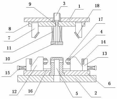
[0011] As an embodiment of the present invention, such as figure 1 Shown, a kind of punching side hole mold comprises upper die base 1, lower die base 2, die handle 3, punch 4 and die 5, and die 5 is fixed on the lower die base 2 by die fixing plate 6; The opposite sides of the side wall of the die 5 are symmetrically provided with die holes, and the upper surface of the die fixing plate 6 and the two sides corresponding to the die holes are provided with chute respectively and are respectively provided with oblique sliders 12 and stoppers 13, which can be slanted. The block 12 can slide along the chute, the stopper 13 is arranged on the side of the inclined slide 12 away from the die 5, the side of the inclined slide 12 close to the die 5 and the position corresponding to the die hole is provided with the punch 4, and the punch 4 The surface of the side wall is covered with a rubber pressing block 17; the end of the inclined slider 12 away from the die 5 is provided with an i...


PUM


Abstract

The invention discloses a side hole punching die, and relates to a stamping die. The die comprises an upper die holder, a lower die holder, a die handle, a male die and a female die, wherein two sides of the upper surface of a fixed plate of the female die corresponding to a female die hole are respectively provided with a chute, a slanted slide block and a stop block; the male die is arranged at a position of the slanted slide block close to the lateral surface of the female die corresponding to the female die hole; a rubber press block is coated on the surface of the lateral wall of the male die; a guide hole is formed on the stop block; a pull rod passes through the guide hole and is fixedly connected to the end face of the slanted slide block far from the female die, and the end of the pull rod far from the slanted slide block is provided with a stopper; a return spring is arranged on the pull rod between the stopper and the stop block; slanted wedges matched with the slanted slide block are arranged at two ends of the upper die holder corresponding to the slanted slide block; a wear-resistant pad is arranged on a working inclined plane of each slanted wedge; and a guide block is arranged on the lateral surface of the stopper corresponding to each slanted wedge. In the side hole punching die, two symmetrical holes on the lateral wall of a workpiece can be formed at one time without repeated positioning, so that the production rate and the product accuracy are improved.

Description

technical field [0001] The invention relates to a stamping die, in particular to a side hole punching die. Background technique [0002] In stamping production, it is often necessary to punch holes on the side walls of rotary workpieces (such as cylindrical parts, box-shaped parts, large covering parts, etc.), generally using a cantilever punching die. The die of this die is set horizontally. Put the workpiece that needs to punch the side hole on the die, and the vertical punch moves downward under the drive of the press to complete the forming of the side hole. If the rotary workpiece needs to punch two holes symmetrically on the side wall, To use the existing cantilever punching die, it is necessary to punch a hole on one side first, and then rotate the workpiece 180 degrees to punch another hole, which requires repeated positioning, which is very inconvenient and low in productivity, and if the positioning is not accurate after rotation It often results in low accuracy o...

Claims


Application Information

Patent Timeline
Patent Type & Authority Applications(China)
IPC IPC(8): B21D28/34
Inventor 王良全
Owner 王良全
Features
  • R&D
  • Intellectual Property
  • Life Sciences
  • Materials
  • Tech Scout
  • Unparalleled Data Quality
  • Higher Quality Content
  • 60% Fewer Hallucinations
Learn More