Eureka AIR delivers breakthrough ideas for toughest innovation challenges, trusted by R&D personnel around the world.

Double-toggle rod type four-hammer forging device

A technology of double toggle levers and four hammer heads, which is applied in the driving device of hammer, forging/pressing/hammer device, hammer, etc., can solve the problems of harsh working surface lubrication requirements, high friction force, and difficulty in sealing the lubricant.

Inactive Publication Date: 2012-01-04
TAIYUAN UNIVERSITY OF SCIENCE AND TECHNOLOGY
View PDF6 Cites 5 Cited by
  • Summary
  • Abstract
  • Description
  • Claims
  • Application Information

AI Technical Summary

Problems solved by technology

The movement of the upper and lower hammer heads in the above two patents is realized by the movement of the press, the movement of the two side hammer heads is realized by the relative movement of the upper and lower hammer heads on a 40-50 degree slope, and the horizontal component force of the side hammer heads is generated by the slope. The size of the horizontal component force is affected by the supporting area of ​​the hammer head, and the whole process is sliding friction, the friction force is large, the lubrication requirements of the working surface are strict, and the lubricant is difficult to seal

Method used


Image

  • Double-toggle rod type four-hammer forging device
  • Double-toggle rod type four-hammer forging device

Examples


Embodiment Construction

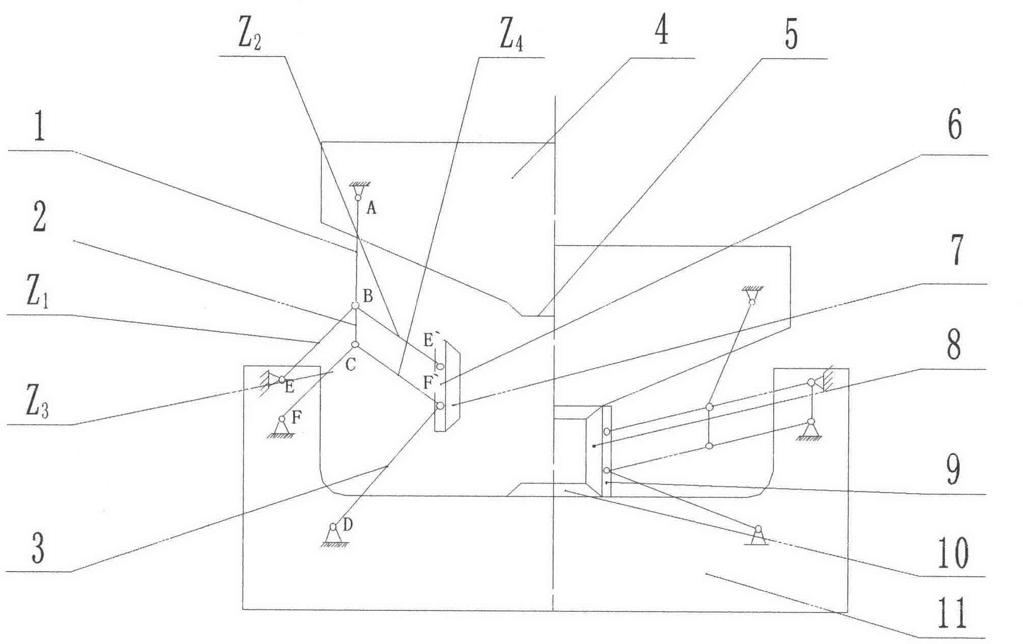
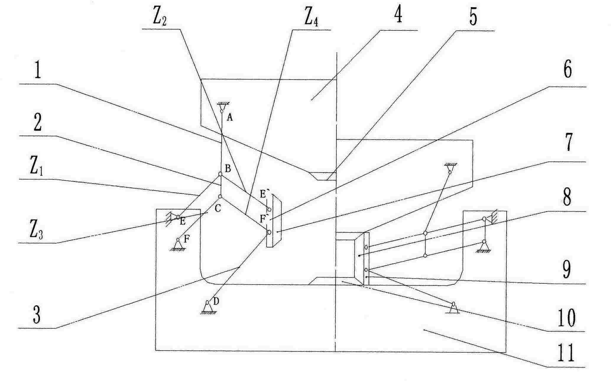
[0011] like figure 1 As shown, the device is installed on the hydraulic press, the lower anvil 11 is fixedly connected with the workbench, and the upper anvil 4 is fixedly connected with the movable beam. When the hydraulic press is started, the movable crossbeam drives the upper anvil 11 and the upper hammer head 5 to apply downward pressure, and drives the left and right double toggle mechanisms to push the left and right sliders 6, 9 and the left and right hammer heads 7, 8 to extrude and forge toward the center of the billet. , forming four hammerheads up, down, left, and right to simultaneously extrude and forge toward the center of the billet. The billet can only be deformed in the axial direction due to the effect of extrusion forging, and then the movable beam is lifted upwards to drive the upper anvil and the upper hammer to be lifted upwards. The left and right side sliders and side hammer heads are pulled apart by the left and right double toggle mechanisms, and the...


PUM


Abstract

The invention provides a double-toggle rod type four-hammer forging device, and belongs to the field of metal pressure processing machines. The device comprises an upper anvil block, a lower anvil block, an upper hammer, a lower hammer, a left side slide block, a right side slide block, a left side hammer and a right side hammer, and is characterized in that: double-toggle rod mechanisms are symmetrically arranged on left and right sides of the upper and lower anvil blocks respectively; each double-toggle rod mechanism consists of an oscillating rod, a connecting rod, a toggle rod and a guiderod, the upper end of the oscillating rod is hinged with a fixed point on the upper anvil block, and the lower end which is a movable point of the oscillating rod is hinged with the upper end of the connecting rod, the upper end of the toggle rod Z1 and the upper end of the toggle rod Z2 respectively; the lower end which is a movable point of the connecting rod is hinged with the upper end of thetoggle rod Z3 and the upper end of the toggle rod Z4 respectively; the lower end of the toggle rod Z1 and the lower end of the toggle rod Z3 are hinged with the fixed point of the lower anvil block respectively; the lower end of the toggle rod Z2 and the lower end of the toggle rod Z4 are hinged with the fixed point on each side slide block respectively; the upper end of the guide rod is hinged with the fixed point on each side slide block; and the lower end of the guide rod is hinged with the fixed point of the lower anvil block. The device has the advantages that: sliding friction is changed into pivoting friction to reduce energy consumption and save energy; meanwhile, positions of the four hammers are changed along with the change of the diameter of a blank, the distances among the hammers can be regulated by changing the lengths and proportion of the connecting rods and the toggle rod mechanisms so as to regulate the diameter range of the forging blank.

Description

technical field [0001] The invention belongs to the field of metal pressure processing machinery, and in particular relates to a double toggle-type four-hammer forging device. Background technique [0002] In recent years, with the development of social economy and the requirements of environmental protection and energy saving, fast and efficient forging is becoming more and more important, especially for difficult-to-deform materials. In addition, the investment in large presses, the full and effective use of high-power presses, and the increase in the workload of large presses are also problems that need to be solved urgently in China. [0003] The traditional free forging hydraulic press only relies on the upper and lower hammers to extrude the billet to deform in the axial and transverse directions to complete the forging work. Due to the transverse deformation, not only the elongation efficiency is low, but also difficult to deform, and it is very easy to crack on the t...

Claims


Application Information

Patent Timeline
IPC IPC(8): B21J7/14B21J7/20
Inventor 孙述利何文武
Owner TAIYUAN UNIVERSITY OF SCIENCE AND TECHNOLOGY
Why Eureka
Eureka Blog
Learn More