Built-in plug door device for rail vehicle

A rail vehicle and door leaf technology, which is applied in the field of built-in sliding door devices for rail vehicles, can solve problems such as uneven appearance, poor aerodynamic characteristics, and reduce the 2' width of the vehicle body, so as to improve safety and sealing. reliability, improve ride comfort, and solve the effect of smooth appearance

Active Publication Date: 2012-01-04
NANJING KANGNI MECHANICAL & ELECTRICAL
View PDF14 Cites 39 Cited by
  • Summary
  • Abstract
  • Description
  • Claims
  • Application Information

AI Technical Summary

Problems solved by technology

[0003] The following problems exist in the use of the swing-out sliding door: (1) The 2' width of the car body is reduced: usually, the automatic door system is symmetrically arranged on both sides of the railway vehicle, so the space on both sides is about 140mm due to the swinging out of the door
This solution meets the 2' wide car body and safety requirements, but there are still the following problems: (1) high-speed operation, especially when the operating speed is greater than 250km / h, the aerodynamic characteristics are poor, the running resistance is large, and the energy consumption is high; (2) The appearance is not smooth, and the existence of height difference makes the aerodynamic noise larger during operation; (3) There is a certain height between the door leaf 1' and the outer wall, which affects the appearance of the vehicle; (4) Vehicles with built-in side sliding doors Not suitable for mechanized operations when cleaning in the door area
Since the door leaf protrudes outside the car body, there are the following problems: (1) the aerodynamic characteristics of the vehicle are poor when running, and the noise is loud at high speed; (2) the protruding door leaf occupies the gap between the vehicle and the platform, making the width of the car body Affected, the hull cannot be too wide

Method used


Image

  • Built-in plug door device for rail vehicle
  • Built-in plug door device for rail vehicle
  • Built-in plug door device for rail vehicle

Examples


Embodiment Construction

[0026] The embodiments of the present invention are described in detail below. This embodiment is implemented on the premise of the technical solution of the present invention, and detailed implementation methods and specific operating procedures are provided, but the protection scope of the present invention is not limited to the following implementation example.

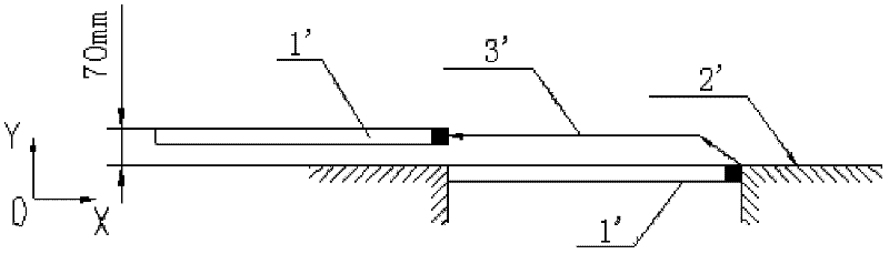
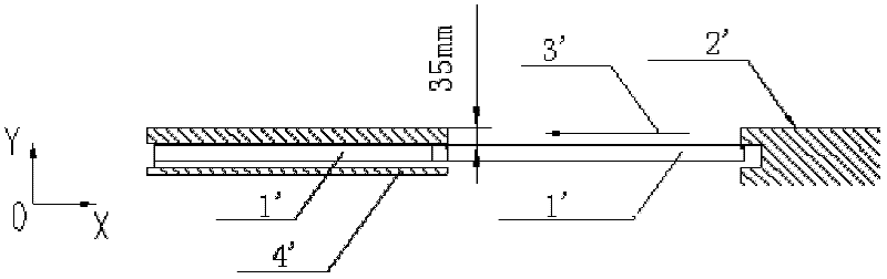
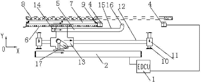
[0027] Such as image 3 As shown, this embodiment includes a control mechanism 1, a drive mechanism 2, a bearing mechanism 3, a pressing mechanism 4, a guide chute 5, a side wall partition 6, a door leaf 7, a car body 8 and a sealing mechanism 9; the side wall partition 6 is located at On the inner side of the car body 8, an interlayer is formed between the side wall partition wall 6 and the car body 8, and the size of the interlayer matches the door leaf 7; The inner side of the body 8; the carrying mechanism 3 includes a guide column 10, two sleeves 11, a connecting rod 12, a slider 13 and a guide wheel 14; wher...


PUM


Abstract

The invention discloses a built-in plug door device for a rail vehicle. The device comprises a control mechanism, a driving mechanism, a bearing mechanism, a compaction mechanism, a guide chute and a door leaf; the bearing mechanism comprises a guide post, two sleeves, a connecting rod, a sliding block and a guide wheel; and the control mechanism is respectively connected with the driving mechanism and the compaction mechanism. The advantages of an outward swing plug door and a built-in side sliding door are combined in the built-in plug door device, and the problem of smooth appearance of the built-in side sliding door is solved by plug movement; the outer side of the body is smoother, the influence of high-speed running pressure wave on the door leaf is reduced, and high-speed running noise is reduced; the body is 140 millimeters wider than the body using the outward swing plug door; and when the plug process of the door leaf is finished, the door leaf is compacted on the body, and the possibility that the door leaf drops outwards is totally limited, so safety and sealing reliability are improved.

Description

technical field [0001] The invention relates to a door device used for rail vehicles, in particular to a built-in sliding door device for rail vehicles. Background technique [0002] At present, the entrance automatic door systems of high-speed trains, main line trains and urban rail trains at home and abroad are basically divided into three categories: swing-out sliding doors, built-in side sliding doors and external sliding doors. Such as figure 1 As shown, the swing-out sliding door mainly drives the opening and closing of the door leaf 1' through the driving device. The key features are: when the door is closed, the outside of the door leaf 1' is flush with the outside of the vehicle, and when the door is opened, it faces the outside of the car body 2' ( Y direction) swing out, usually about 70mm, 3' in the figure is the motion track of the door leaf 1'. [0003] The following problems exist in the use of the swing-out sliding door: (1) The 2' width of the car body is ...

Claims


Application Information

Patent Timeline
Patent Type & Authority Applications(China)
IPC IPC(8): B61D19/00E05F15/00
CPCB61D19/005Y02T30/30E05D2015/1071B61D19/026E05Y2900/51E05D15/1068E05F15/655E05Y2201/412E05Y2400/41Y02T30/00
Inventor 史翔丁瑞权刘落明黄强王星明郭丽娜
Owner NANJING KANGNI MECHANICAL & ELECTRICAL
Why Eureka
Try Eureka