Structure of electric power sensor matched with rear fork of bicycle

An electric power assist, bicycle technology, applied in bicycle accessories, vehicle parts, rider drive and other directions, to achieve the effects of convenient installation and maintenance, good magnetic induction effect, and high degree of response

Inactive Publication Date: 2012-01-04
WUXI SHANGGE IND DESIGN
View PDF9 Cites 34 Cited by
  • Summary
  • Abstract
  • Description
  • Claims
  • Application Information

AI Technical Summary

Problems solved by technology

[0004]The moving plate in the sensor part of this patent is set on the central axis, and the fixed plate is set on the car body. From the analysis of its mechanical structure, there are the following defects: First, the distance between the setting positions of the moving plate and the fixed plate is relatively large, the magnetic induction intensity is weak, and the sensing coefficient is reduced. The requirements for components and permanent magnetic steel are relatively strict, which increases the production cost; second, the moving plate and fixed plate take up a lot of space, the moving plate is combined with the central shaft, and the fixed plate is combined with the car body. It is inconvenient to work separately
The patented sensor part is magnetically fitted around the bicycle brake and the wheel. The magnetic induction part of the sensor is fixed on the brake and the brake arm. The wheel needs to be connected with a magnet for coordination. There are also defects of poor magnetic response sensitivity and low magnetic induction intensity. And the installation is troublesome, and higher requirements are put forward for the machining accuracy of the wheels, which is not conducive to popularization

Method used


Image

  • Structure of electric power sensor matched with rear fork of bicycle
  • Structure of electric power sensor matched with rear fork of bicycle
  • Structure of electric power sensor matched with rear fork of bicycle

Examples


Embodiment Construction

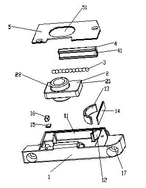
[0022] Attached below figure 1 And attached Figure 5 Embodiments of the invention are illustrated:

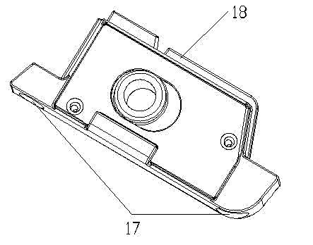
[0023] A structure of an electric power-assisted sensor that cooperates with the rear fork of a bicycle. There is a box body 1, a Hall element 15 is installed on one side of the bottom of the box body 1, and a long slot hole 51 passing through the bottom of the box body 1 is also accommodated in the box body 1. The sensor assembly is movable, and a permanent magnet 16 arranged on the sensor assembly is magnetically coupled with the Hall element 15 on the box body 1; the bicycle rear axle 1 is limited to move in the long slot hole 51 at the bottom of the box body 1 Therefore, when the rear axle 6 is used to move, the magnetic induction between the relatively fixed permanent magnet 16 and the Hall element 15 changes with the rear axle 6, and the electric signal is output to control the force rotation of the bicycle motor.

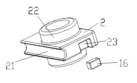
[0024] The sensor assembly includes a positioning bl...


PUM


Abstract

The invention discloses a structure of an electric power sensor matched with a rear fork of a bicycle. The structure is provided with a box body, a Hall element is arranged at one side of the bottom of the box body, a sensor assembly passing through an elongated slot hole at the bottom of the box body and being in a movable state is held in the box body, and a permanent magnet arranged on the sensor assembly is in magnetic induction fit with the Hall element on the box body; a rear axle of the bicycle is limited to move in the elongated slot hole at the bottom of the box body; and by using the magnetic induction change between the permanent magnet fixed relative to the rear axle and the Hall element when the rear axle moves, an electrical signal is output to control stress application rotation of a bicycle motor. The rear fork of the bicycle is fully used as the carrier of the sensor, the whole sensor component is skillfully arranged in the box body, and the box body is arranged on the rear fork of the bicycle, so that the structure has the characteristics of good magnetic induction effect, high response degree and convenience for installation and maintenance.

Description

Technical field [0001] [0002] The invention involves the field of bicycle transmission, especially the structure of a bicycle electric help sensor, Background technique [0003] In the field of bicycle electric assistance sensors, China Patent ZL03264387.X revealed a "timeliness electric help bicycle sensor".The difference between the time used and the torque applied by the people's pedaling and the speed of the bicycle is indirectly measured, so as to implement automatic control of the bicycle speed; two round disks, one is called a dynamic disk, and the other is called a fixed disk.The dynamic plate is fixed on the central axis of the bicycle, which is inlaid with permanent magnetic steel on it, and there is no wire connection with the car body.The fixed plate is fixed on the car body, and it is inlaid with Hall components on it.The magnetic steel on the dynamic disk is on the same circle on the same circle. During the rotation process, the two are interacted, but there is n...

Claims


Application Information

Patent Timeline
Patent Type & Authority Applications(China)
IPC IPC(8): B62M6/50
CPCB62K25/02B62M6/50
Inventor 王欢
Owner WUXI SHANGGE IND DESIGN
Why Eureka
Try Eureka