

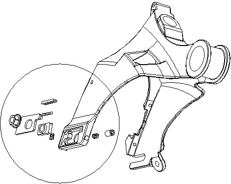
Structure of electric power sensor on bicycle rear fork
An electric power assist and bicycle technology, which is applied to bicycle accessories, vehicle components, and rider drives, etc., can solve the problems of inconvenience, reduced sensor coefficient, weak magnetic induction intensity, etc., and achieves convenient installation and maintenance, good magnetic induction effect, and responsive high degree of effect
- Summary
- Abstract
- Description
- Claims
- Application Information
AI Technical Summary
Problems solved by technology
Method used
Image

Examples
Embodiment Construction
[0018] Attached below figure 1 And attached Figure 5 Embodiments of the invention are illustrated:
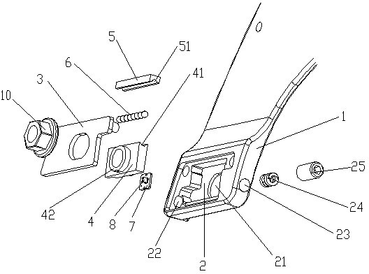
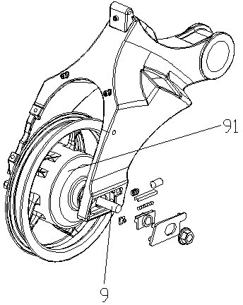
[0019] see figure 2 , image 3 with Figure 4 , a structure of an electric power-assisted sensor on the rear fork of a foldable electric bicycle is provided. A groove 2 is arranged at the bottom of one side of the rear fork 1 of the bicycle, and a Hall element is fixedly arranged in the groove 2. The circuit board 7, the groove 2 also contains a sensor assembly on the rear axle 9 that passes through the slot 21 at the bottom of the groove 2 and is movable. The sensor assembly includes a positioning block 4 arranged on the rear axle 9, The upper part of the positioning block 4 located in the groove 2 is provided with a lower guide rail 41, a fixed bar 5 is arranged above the positioning block 4, and an upper guide rail 51 is provided at the bottom of the fixed bar 5, and the upper guide rail 51 and the lower guide rail 41 are provided with Ball or ball strip 6; see Figu...
PUM
 Abstract
Description
Claims
Application Information