Transporting device for machining workpiece

A technology for transportation devices and workpieces, which is applied in the directions of manual conveying devices, transportation and packaging, mechanical conveyors, etc., can solve the problem of high transfer costs of machined workpieces, reduce the cost of mechanical equipment and power, and overcome the problems of large horse-drawn carts, The effect of avoiding damage

Inactive Publication Date: 2012-01-04
CHENGDU KESHENG PETROLEUM TECH +1
View PDF5 Cites 6 Cited by
  • Summary
  • Abstract
  • Description
  • Claims
  • Application Information

AI Technical Summary

Problems solved by technology

[0003] The object of the present invention is to provide a workpiece transfer device for machining, which overcomes the problem of high transfer cost of machining workpieces

Method used


Image

  • Transporting device for machining workpiece
  • Transporting device for machining workpiece
  • Transporting device for machining workpiece

Examples


Embodiment

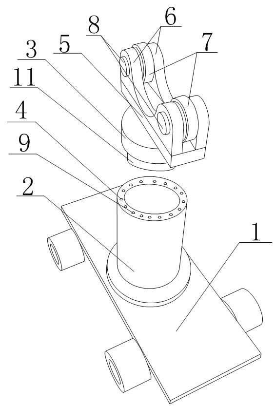
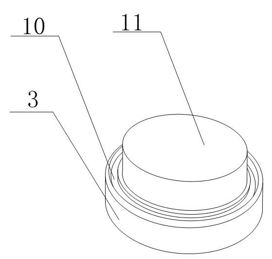
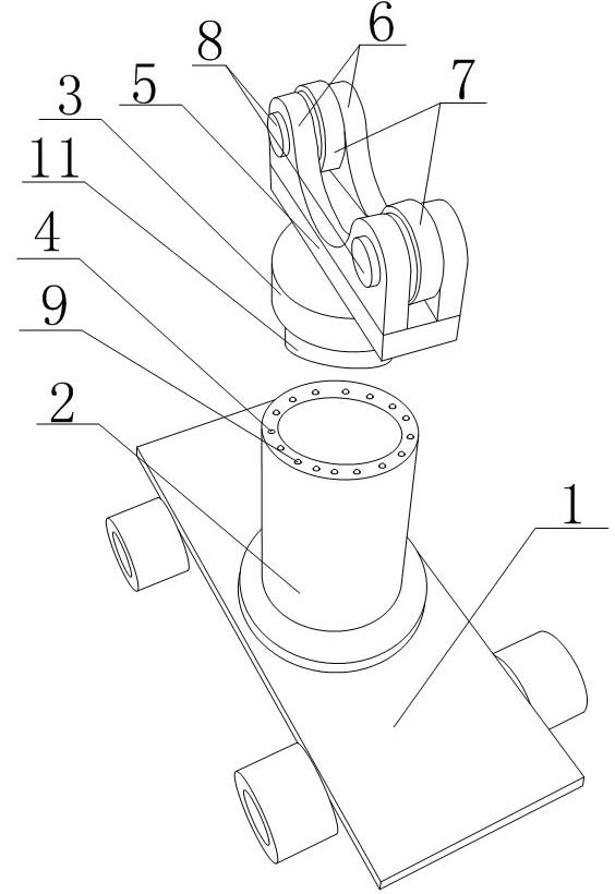
[0019] Such as figure 1 As shown, a transport device for machining workpieces of the present invention includes a transport vehicle 1, the transport vehicle includes a vehicle body and wheels, a support column 2 is arranged on the vehicle body, the support column 2 is a hollow cylinder, and the support column 2 Several circular grooves are arranged on the side wall of the top, and the grooves surround the top of the support column 2 to form a ring shape, and balls 9 are placed in the grooves; The lower part is provided with a guide column 11 matching the inner diameter of the support column 2, and an annular groove 10 surrounding the guide column 11 is provided on the rotating platform 3. The annular groove 10 is located on the ball 9, and the width of the annular groove 10 is the same as that of the ball. 9 matches the diameter, the sum of the depth of the annular groove 10 and the depth of the groove where the ball 9 is placed is less than or equal to the diameter of the bal...


PUM


Abstract

The invention discloses a transporting device for machining a workpiece. The transporting device comprises a transporting vehicle (1) and a supporting pillar (2), wherein the supporting pillar (2) is in a hollow cylindrical structure, a rotating bearing platform (3) is arranged on the supporting pillar (2), the top of the supporting pillar (2) is provided with a circle of round groove (4) in which roll balls (9) are put, the bottom of the rotating bearing platform (3) is provided with an annular slot (10) which is in fit with the roll balls (9), and the top of the rotating bearing platform (3) is provided with a workpiece storage device. The transporting device provided by the invention reduces the mechanical apparatus cost and the power cost, and avoids the condition that a middle-sized workpiece uses a crane or other tools,; the resources are reasonably distributed and used; and meanwhile, the roll balls in the circle of round groove arranged at the top of the supporting pillar can reduce the friction between the rotating bearing platform and the supporting pillar when the rotating bearing platform rotates, and are in favor of the transferring of the workpiece.

Description

technical field [0001] The invention relates to a transport device, in particular to a transport device for machining workpieces. Background technique [0002] Machining is a process in which machining machinery is used to change the shape or performance of a workpiece. According to the temperature state of the processed workpiece, it is divided into cold processing and hot processing: generally processing at room temperature, and does not cause chemical or physical phase changes of the workpiece, it is called cold processing; generally processing at a state higher or lower than normal temperature will be The chemical or phase change caused by the workpiece is called thermal processing. Cold processing can be divided into cutting processing and pressure processing according to the difference in processing methods; thermal processing commonly includes heat treatment, forging, casting and welding. Machining includes: filament power winding, laser cutting, heavy machining, me...

Claims


Application Information

Patent Timeline
Patent Type & Authority Applications(China)
IPC IPC(8): B65G7/02B65G35/00
Inventor 贺昶明
Owner CHENGDU KESHENG PETROLEUM TECH
Why Eureka
Try Eureka