Connection structure and connection method of heat exchange tube and tube plate

A connection structure and connection method technology, which is applied to the structure where the tube sheets are connected together. In the field of heat exchange tubes, it can solve the problems of breaking, large thermal expansion, and pulling off the tubes, etc., and achieves convenient assembly process, good sealing performance, The effect of ensuring the accuracy of processing and assembly

Active Publication Date: 2012-01-04
SICHUAN BLUSR MACHINERY
View PDF5 Cites 14 Cited by
  • Summary
  • Abstract
  • Description
  • Claims
  • Application Information

AI Technical Summary

Problems solved by technology

Its disadvantages are: there is a certain gap between the tube and the tube sheet (forming a dead zone), and the fluid does not flow in the gap, which is prone to galvanic corrosion. When the tubes at both ends are welded, if the thermal expansion is large and due to technological reasons If expansion joints cannot be used for thermal compensation, it is easy to pull off the tube sheet and the tube or break the tube
[0007] When it is necessary to ensure that the tube sheet and heat exchange tubes are not affected by the thermal expansion of the heat exchange tubes and the expansion joint cannot be installed on the equipment due to the structural reasons of the equipment, the above connection structure and method are no longer applicable
Therefore, the connection of tubes and tube sheets under specific process conditions that do not allow welding and expansion has become a difficult problem in the design and manufacture of shell and tube heat exchangers.

Method used


Image

  • Connection structure and connection method of heat exchange tube and tube plate
  • Connection structure and connection method of heat exchange tube and tube plate
  • Connection structure and connection method of heat exchange tube and tube plate

Examples


Embodiment Construction

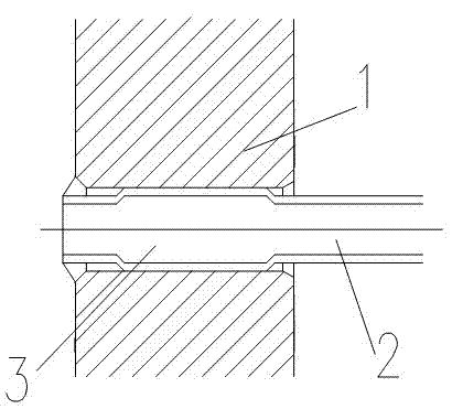
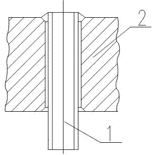
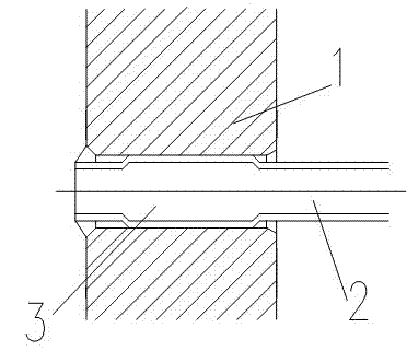
[0029] Specific embodiment 1 of the present invention, the connection structure of heat exchange tube and tube sheet, such as Figure 4 As shown, the main body is composed of a tube plate 1, a heat exchange tube 2, a threaded plug 5, and an "O"-shaped sealing ring 4. There is an annular sealing groove and a section of internal thread on the inner wall of the heat exchange tube hole on the tube plate 1. , where the internal thread is closer to the heat exchange nozzle (that is, the end face of the tube sheet) than the annular sealing groove to the heat exchange nozzle, and the heat exchange tube 2 is sleeved with an "O" shape on the inner section of the heat exchange tube hole The sealing ring 4, the "O" type sealing ring 4 cooperates with the annular sealing groove and the heat exchange tube. This connection structure also includes a threaded plug 5, and the outer wall of the threaded plug 5 has a thread that matches the inner thread of the tube hole on the tube plate. There i...


PUM

PropertyMeasurementUnit
lengthaaaaaaaaaa
lengthaaaaaaaaaa

Abstract

The invention discloses a connection structure of a heat exchange tube and a tube plate. The connection structure comprises the tube plate and the heat exchange tube. The connection structure is characterized in that: a section of annular sealing groove and a section of internal thread are formed on an inner wall of a heat exchange tube hole in the tube plate; a distance between the internal thread and a heat exchange tube orifice (namely an end face of the tube plate) is smaller than the distance between the annular sealing groove and the heat exchange tube orifice; an O-shaped sealing ring is sleeved on the inner section of the heat exchange tube hole of the heat exchange tube; and the O-shaped sealing ring is placed in the annular sealing groove and in fit with the annular sealing groove and the heat exchange tube. The connection structure also comprises a threaded plug, wherein threads which are in fit with the internal thread of the tube hole in the tube plate are formed on an outer wall of the threaded plug; a hollow hole is formed inside the threaded plug; the inner wall of the hole is in fit with the outer wall of the heat exchange tube; a shrinkage step is arranged in thehole; a clearance is reserved between the step and the heat exchange tube orifice; and the material hardness of the threaded plug is lower than that of the tube plate. In the situation that the heat expansion amount of the heat exchange tube cannot influence the connection of the tube plate and the heat exchange tube, the connection structure has excellent sealing performance.

Description

technical field [0001] The invention relates to the manufacturing technology of a shell-and-tube heat exchanger in a pressure vessel (made of steel), in particular to a structure and a method for connecting heat exchange tubes and tube sheets together. Background technique [0002] In the design and manufacture of shell and tube heat exchangers, the connection between the tube and the tube sheet is very important. The general requirements for the connection are: good sealing, if there is leakage at the connection, the two (medium) fluids will leak together, causing an accident; there is sufficient resistance to pull-off, otherwise the temperature difference stress and the tube side and shell Under the action of the process pressure difference, the connection between the tube and the tube sheet will be pulled off, or the heat exchange tube will be broken. [0003] The existing connection methods of heat exchange tubes and tube sheets in shell-and-tube heat exchangers include...

Claims


Application Information

Patent Timeline
Patent Type & Authority Applications(China)
IPC IPC(8): F28F9/26B23P11/00
Inventor 秦国安张泽顺梅奇罗晓成李华梁洪明曾兴亮张继云汪益均
Owner SICHUAN BLUSR MACHINERY
Why Eureka
Try Eureka