Eureka AIR delivers breakthrough ideas for toughest innovation challenges, trusted by R&D personnel around the world.

Differential type vertical micro-force loading device and method

A loading device, differential technology, applied in the direction of measuring device, measuring force, force/torque/work measuring instrument calibration/test, etc. The effect of eliminating bending deformation and bending stress, improving force loading accuracy, and eliminating the effect of temperature

Inactive Publication Date: 2012-01-04
HEFEI UNIV OF TECH
View PDF5 Cites 6 Cited by
  • Summary
  • Abstract
  • Description
  • Claims
  • Application Information

AI Technical Summary

Problems solved by technology

However, compared with its research and production, the development of the performance measurement of the micro force sensor itself appears to be relatively lagging behind.
At present, the routinely used pulley weight method cannot carry out micro-force loading; there are already Lorentz force and electrostatic force calibration methods, which cause instability due to many affected factors; in recent years, the application of micro-force using piezoelectric elements has become more and more More and more, but this method is costly, complicated to operate, and produces a small force range
[0003] The flexible hinge mechanism has been widely used in the fields of precision measurement and calibration, but there is still a lack of comprehensive consideration and research on the influence of the deformation of the flexible hinge, the position of the center of gravity of the lever, and the changes in temperature on the accuracy of measurement and calibration. Relevant structural design influenced by two factors of temperature and temperature, and in order to obtain higher accuracy when calibrating or measuring micro force, it is necessary to solve the influence of the above aspects on the calibration or measurement of micro force, because gravity and temperature The impact may be far greater than the maximum range of micro-force loading, which will have a fatal impact on micro-force loading

Method used


Image

  • Differential type vertical micro-force loading device and method
  • Differential type vertical micro-force loading device and method

Examples


Embodiment Construction

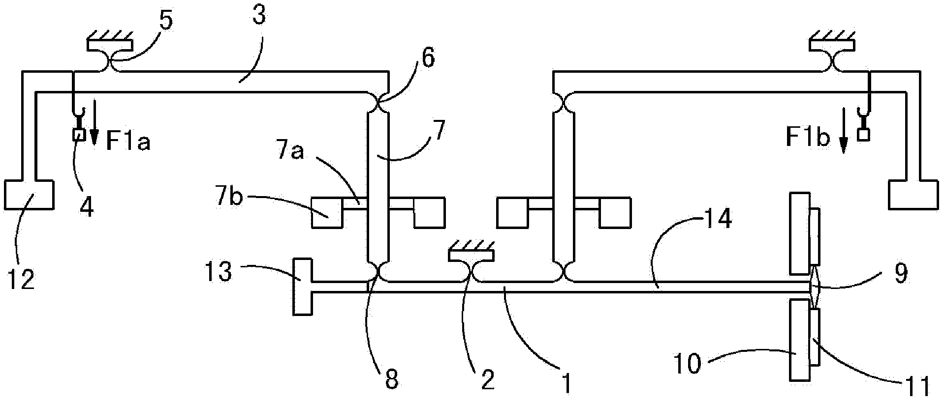
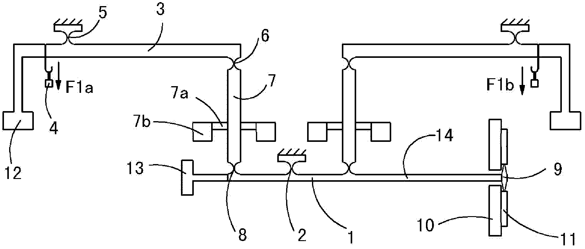
[0021] see figure 1 , the differential vertical micro-force loading device of this embodiment includes: a pair of primary levers 3, a secondary lever 1, a pair of transition bars 7, a pair of primary lever counterweights 12, a pair of cantilever arms 7a, a pair of Transition lever counterweight 7b and a secondary lever counterweight 13; in this embodiment, the secondary fulcrum 2 is set in the middle of the secondary lever 1 placed horizontally, with the secondary fulcrum 2 as the center, in the same vertical In the plane, a pair of first-level levers 3 are symmetrically located on both sides of the second-level fulcrum 2, and are connected to the second-level lever 1 through the transition rods 7 on their respective sides;

[0022] The first-level lever 3 is placed horizontally, the loading weight 4 is set at the outer end of the first-level lever as the input end, the first-level fulcrum 5 is located in the middle of the first-level lever 3, and the inner end of the first-le...


PUM


Abstract

The invention discloses a differential type vertical micro-force loading device and method, which is characterized in that a secondary pivot horizontally placed at the middle of a secondary lever, a pair of primary levers is symmetrically distributed at two sides of the secondary pivot in one vertical plane with the secondary pivot as a center, and the primary levers are respectively linked with the secondary lever by a transition lever at own side. The differential type vertical micro-force loading device and method can be used for calibrating micro-force sensors, microelectromechanical systems, and various micro-force detectors, and provides support for the force measuring system of the micro-force.

Description

technical field [0001] The invention relates to a micro force loading device applied in the technical field of measurement. Background technique [0002] With the vigorous development of modern science and technology, there are more and more occasions that require small force values, such as the study of mechanical properties of micro-scale components in micro-electromechanical systems, measurement of micro-friction phenomena, micro-force detection in micro-sensing and micro-robot assembly, etc. Therefore, the research, production, and production of micro force sensors will follow. But compared with its research and production, the performance measurement development of the micro force sensor itself appears to be relatively lagging behind. At present, the routinely used pulley weight method cannot carry out micro-force loading; there are already Lorentz force and electrostatic force calibration methods, which cause instability due to many affected factors; in recent years, ...

Claims


Application Information

Patent Timeline
Patent Type & Authority Applications(China)
IPC IPC(8): G01L25/00G01L1/00
Inventor 王勇刘晓峰王秋杰刘焕进刘正士
Owner HEFEI UNIV OF TECH
Why Eureka
Eureka Blog
Learn More