Device used for filtering, dehumidificating and mixing smoke

A flue gas and mixing chamber technology, which is used in the field of flue gas filtration, dehumidification and mixing devices, can solve the problems of huge sampling and analysis workload, long sampling duration, and large pipeline section.

Inactive Publication Date: 2012-01-04
赵勇纲
View PDF6 Cites 13 Cited by
  • Summary
  • Abstract
  • Description
  • Claims
  • Application Information

AI Technical Summary

Problems solved by technology

Due to the large capacity of the current unit and the large cross-section of the pipeline, the workload of sampling and analysis is huge, and the sampling duration is long, so it is impossible to simultaneously sample the entire measured cross-section
In addition, due to the high dust and moisture content in the flue gas, it often leads to failure of the flue gas analysis device

Method used


Image

  • Device used for filtering, dehumidificating and mixing smoke
  • Device used for filtering, dehumidificating and mixing smoke

Examples


Embodiment Construction

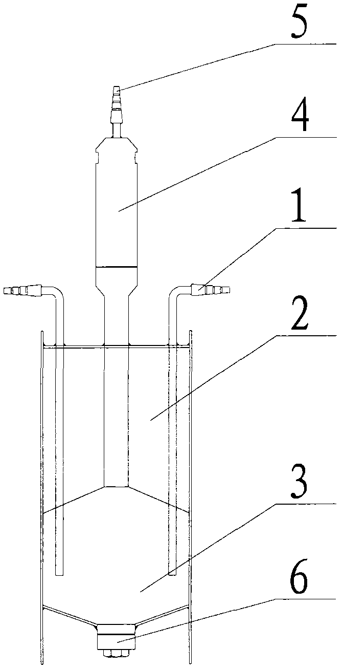
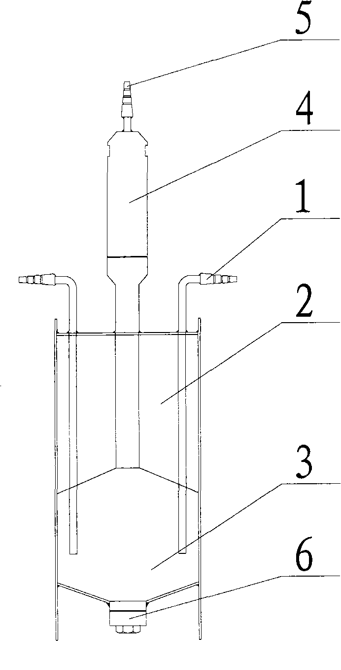
[0010] The present invention will be described in further detail below in conjunction with the accompanying drawings.

[0011] like figure 1 As shown, the device is composed of the following six main parts: flue gas introduction pipe 1, dehumidification chamber 2, mixing chamber 3, filter chamber 4, flue gas outlet pipe 5, and ash discharge port 6. The overall device is in the shape of a cylinder, and the device is divided into the upper part as the dehumidification chamber 2; the lower part as the mixing chamber 3, and a water collecting partition is set between the two. A flue gas introduction pipe 1 and a flue gas extraction pipe 5 are installed in the mixing chamber 3 to pass through the dehumidification chamber 2 and lead to the outside. The flue gas introduction pipe 1 is arranged circularly along the circumference of the cylinder, and the flue gas extraction pipe 5 is located in the center of the cylinder. The lower part of the flue gas outlet pipe 5 is connected with ...


PUM


Abstract

The invention discloses a device used for filtering, dehumidificating and mixing smoke. The device is characterized in that the whole device is in a cylindrical shape; the device is divided into a dehumidification chamber and a mixing chamber; a water collection clapboard is arranged between the dehumidification chamber and the mixing chamber; the mixed chamber is respectively provided with a smoke inlet pipe and a smoke outlet pipe which lead to the outside by virtue of the dehumidification chamber; the lower part of the smoke outlet pipe is connected with a filter chamber; the lower part of the mixing chamber is provided with an ash placing opening; the smoke taken out from different smoke sampling points enters the mixing chamber through the smoke outlet pipe; and the smoke is cooled and dehumidifacted by the dehumidification chamber in the process of entering the mixing chamber; the smoke is mixed in the mixing chamber; dust is settled owning to inertia and gravity, thus the dust is removed; the smoke is cooled again by the smoke outlet pipe and is filtered by the filter chamber; and the uniformly mixed clean smoke after dehumidification and dust removal is guided out to be transmitted to a smoke analysis measuring system through the smoke outlet pipe.

Description

technical field [0001] The invention relates to a device for filtering, dehumidifying and mixing flue gas, in particular to a device for filtering, dehumidifying and uniformly mixing flue gas in the process of sampling, analyzing and testing flue gas. Background technique [0002] In the traditional pipeline flue gas sampling and analysis process, the point-by-point sampling method is used. This method extracts the measured flue gas point by point from the entire measurement section. Due to the large capacity of the current unit and the large cross-section of the pipeline, the workload of sampling and analysis is huge, and the sampling duration is long, so it is impossible to simultaneously sample the entire cross-section to be measured. In addition, due to the high dust and moisture content in the flue gas, the flue gas analysis device often fails. In the process of using the multi-point flue gas sampling method, in order to allow the flue gas analyzer to take in relative...

Claims


Application Information

Patent Timeline
Patent Type & Authority Applications(China)
IPC IPC(8): G01N1/34G01N1/38G01N1/42
Inventor 赵勇纲赵智勇于英利高军周丽琴
Owner 赵勇纲
Why Eureka
Try Eureka