Arc extinguishing chamber of circuit breaker

An arc extinguishing chamber and circuit breaker technology, which is applied to high-voltage air circuit breakers, circuits, electrical components, etc., can solve the problems of slow rise of gas pressure in the compressed air chamber, reducing the gas quality in the compressed air chamber, and hindering the opening movement of the circuit breaker. The effect of prolonging the effective air blowing time, improving the breaking capacity and product reliability, and improving the breaking capacity

Active Publication Date: 2012-01-04
XIAMEN HUADIAN SWITCHGEAR
View PDF7 Cites 8 Cited by
  • Summary
  • Abstract
  • Description
  • Claims
  • Application Information

AI Technical Summary

Problems solved by technology

However, this is not the case. As the energy of the gas in the compression chamber is continuously compressed and the arc burns, it becomes inevitable that the gas pressure in the compression chamber continues to rise. When the pressure of the compression cylinder reaches a high level, a strong The reaction force of the cylinder hinders the opening movement of the circuit breaker, and even reduces the opening speed to zero. figure 1 And attached figure 2 As shown in the travel curve in the oscillogram, there is an obvious stagnation or even rebound during the opening movement of the circuit breaker
[0003] In order to overcome this cylinder reaction force, it is necessary to use a heavy-duty operating mechanism with large operating power and complex structure, such as a hydraulic mechanism, to complete the opening operation of the circuit breaker.
However, according to the survey, the hydraulic mechanism often has leakage problems, and the price is relatively high
[0004] In view of the above-mentioned

Method used


Image

  • Arc extinguishing chamber of circuit breaker
  • Arc extinguishing chamber of circuit breaker
  • Arc extinguishing chamber of circuit breaker

Examples


Embodiment Construction

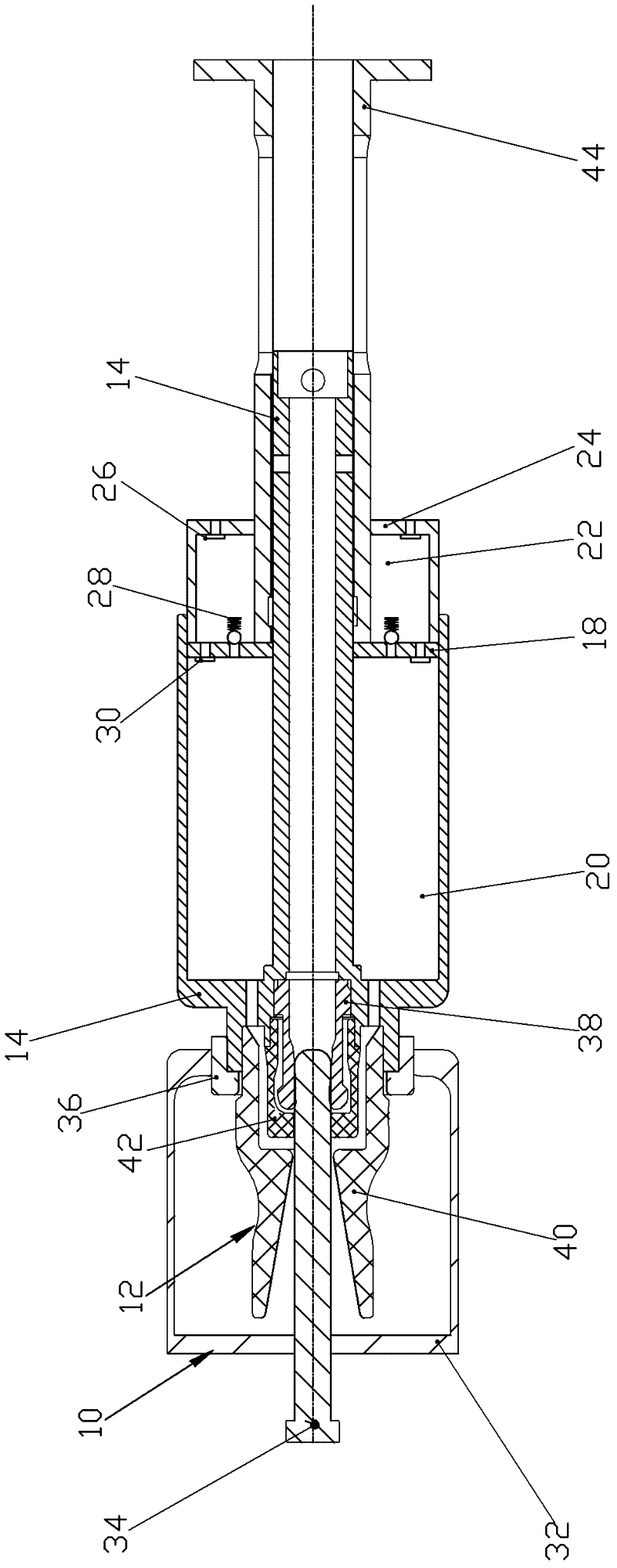
[0026] Please check image 3 and Figure 4 , Circuit breaker interrupter, which includes a static contact module 10, a moving contact module 12, a pressure cylinder 14, a piston 18, a storage chamber 22 and a valve unit.

[0027] The static contact module 10 includes a static main contact 32 and a static arc contact 34 coaxially fixed together.

[0028] The moving contact module 12 includes a moving main contact 36 , a moving arc contact 38 , a large nozzle 40 and a small nozzle 42 . In this embodiment, the moving contact module 12 is matched with the static contact module 10, and the contact and disconnection can be controlled through relative movement. In this embodiment, the moving main contact 36 is compatible with the static main contact 32 , and the moving arc contact 38 is compatible with the static arc contact 34 .

[0029] The cylinder 14 has a cylinder part and a tie rod part, the cylinder part includes a peripheral wall and a front seat arranged at the front end ...


PUM


Abstract

The invention discloses an arc extinguishing chamber of a circuit breaker, which comprises a static contact module (10), a dynamic contact module (12), a gas pressing cylinder (14), a piston (18), a gas storing chamber (22) and a valve unit, wherein a gas pressing chamber (20) is formed between the piston (18) and the gas pressing cylinder (14); the movable contact module (12) and the gas pressing cylinder (14) are connected together; the valve unit is arranged between the gas pressing chamber (20) and the gas storing chamber (22); when a pressure difference between the gas pressing chamber and the gas storing chamber is higher than a preset value, gas in the gas pressing chamber is charged into the gas storing chamber; and when the pressure of the gas storing chamber is higher than the pressure of the gas pressing chamber, gas in the gas storing chamber is poured back into the gas pressing chamber for realizing the process of firstly storing and then supplementing the gas in the gas pressing chamber by the gas storing chamber, so as to generate the following technical effects of: preventing the gas pressing chamber from generating over-high air pressure when the circuit breaker is opened, reducing the operating work of an operating mechanism, extending effective gas blowing time for electric arcs, enhancing opening capability of the circuit breaker and product reliability andreducing the cost of the operating mechanism.

Description

technical field [0001] The invention relates to an arc extinguishing chamber of a circuit breaker. Background technique [0002] The compressed gas type interrupter of the circuit breaker is to extinguish the arc by compressing the gas in the compressed gas chamber to generate the air flow. The existing circuit breaker interrupter includes a static contact module, a moving contact module, a compressed air cylinder and a piston. The piston A compressed air chamber is formed between the compressed air cylinder. The movable contact module is connected with the air cylinder, and the air cylinder drives the movable contact module to move relative to the piston, so as to change the volume of the air chamber. During the opening operation, the gas in the compression chamber is compressed, and the arc combustion causes the gas to expand, so that the gas pressure in the compression chamber rises. When the pressure of the gas in the compression chamber rises to an optimal value (crit...

Claims


Application Information

Patent Timeline
IPC IPC(8): H01H33/91
CPCH01H33/91
Inventor 郑闽生吴忠白刚
Owner XIAMEN HUADIAN SWITCHGEAR
Why Eureka
Try Eureka