Method for modifying sound channel delay parameter of multi-channel signal

A multi-channel signal and delay parameter technology, which is applied in the field of communication, can solve the problems of signal quality degradation, signal frequency domain amplitude attenuation, and affect the quality of multi-channel signals, etc., so as to weaken the comb filter effect and improve the sound image The effect of quality and clarity

Active Publication Date: 2012-01-04
HUAWEI TECH CO LTD
View PDF6 Cites 23 Cited by
  • Summary
  • Abstract
  • Description
  • Claims
  • Application Information

AI Technical Summary

Problems solved by technology

[0007] In the process of realizing the present invention, the inventors have found that there are at least the following problems in the prior art: the processed signals (including: M signal and S signal) obtained after downmixing in the prior art may have a comb filter effect, that is, the M signal The signal frequency domain amplitude in some

Method used


Image

  • Method for modifying sound channel delay parameter of multi-channel signal
  • Method for modifying sound channel delay parameter of multi-channel signal
  • Method for modifying sound channel delay parameter of multi-channel signal

Examples


Embodiment 1

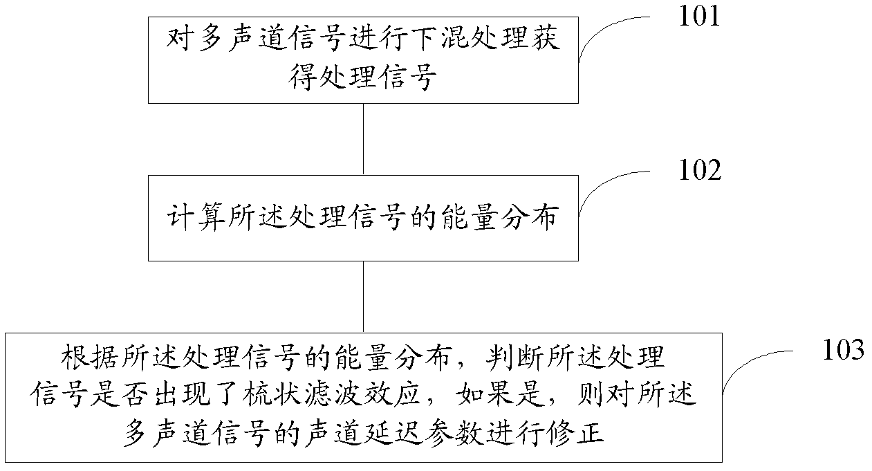
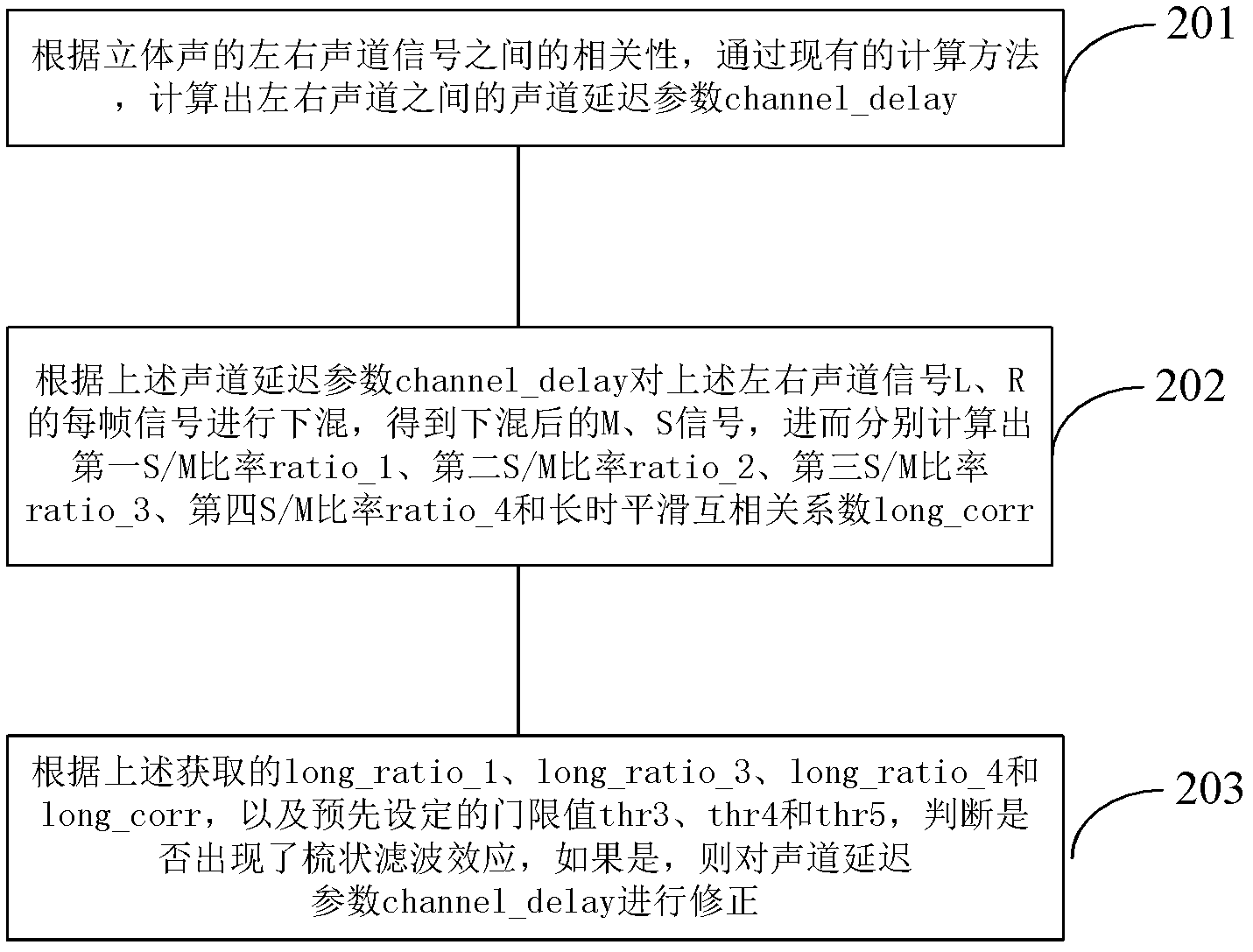
[0030] The processing flow of a method for modifying the channel delay parameters of a multi-channel signal provided by this embodiment is as follows: figure 2 As shown, the following processing steps are included:

[0031] In this embodiment, the input signal is a stereo left channel time-domain signal L k {l 1 , l 2 ,... l N} and the right channel time domain signal R k {r 1 , r 2 ,...r N}, where k represents the kth frame, and N represents a frame of signal with N sampling points.

[0032] Step 201 : Calculate the channel delay parameter channel_delay between the left and right channels corresponding to the current frame according to the correlation between the stereo left and right channel signals.

[0033] Step 202: Downmix the current frame signals of the left and right channel signals L and R according to the channel delay parameter channel_delay to obtain processed signals (M, S signals), and then calculate the first S / M ratio ratio_1, the second The second S...

Embodiment 2

[0098] The difference between this embodiment and the first embodiment lies in that the input signals used for calculating the downmixed M signal and S signal are signals after simple extraction of the original left and right channel signals.

[0099] In this embodiment, for the original input stereo left and right channel time domain signal L k {l 1 , l 2 ,... l N} and R k {r 1 , r 2 ,...r N} to perform simple extraction processing, that is, to perform down-sampling processing to obtain the down-sampled signal L′ k {l' 1 , l' 2 ,...l' M}, R' k {r' 1 , r' 2 ,...r' M}, where M is the number of signal sampling points in one frame after extraction, and k represents the kth frame. The above downsampling processing method is as follows:

[0100] l' j = l N / M×j

[0101] r' j = r N / M×j

[0102] Then, using the downsampled signal L' k {l' 1 , L' 2 ,...l' M}, R' k {r' 1 , r' 2 ,...r' M}, according to the processing flow provided in the first embodiment abov...

Embodiment 3

[0105] In this embodiment, if it is detected that the channel delay parameter needs to be corrected, that is, delay_change_flag=1 is detected in this frame, the trailing range is set, so that all frames in the trailing range after this frame carry out the channel delay parameter Correction, regardless of whether these frames really meet the conditions for the comb filter effect, that is, force the delay correction indicator flag of these frames to be 1. Then, these frame channel delay parameters are corrected according to the four indirect correction methods or direct correction methods in the first embodiment above.

[0106] The frame of the above smear range can be set according to the actual situation, for example, the 100 frames after the frame are set to perform channel delay parameter correction.

[0107] Since the comb filter effect occurs in the current frame, it is very likely that the comb filter effect will continue to appear in subsequent frames. This embodiment i...


PUM


Abstract

The embodiment of the invention provides a method for modifying a sound channel delay parameter of a multi-channel signal. The method mainly comprises the following steps of: carrying out down mixed processing on the multi-channel signal to obtain a processed signal; calculating energy distribution of the processed signal; and judging whether the processed signal generates a comb filtering effect according to the energy distribution of the processed signal, if so, modifying the sound channel delay parameter of the multi-channel signal. According to the method disclosed by the invention, whether the comb filtering effect is generated is judged according to the energy distribution of the processed signal obtained by carrying out down mixed processing on the multi-channel signal, thereby whether the sound channel delay parameter is required to be modified is judged to eliminate the comb filtering effect and further provide better reconstruct stereophonic sound and a sound image and the definition of the multi-channel signal.

Description

technical field [0001] The invention relates to the field of communication technology, in particular to a method for correcting channel delay parameters of multi-channel signals. Background technique [0002] Multi-channel signals have a wide range of application scenarios, such as conference calls, games, etc., and the encoding and decoding of multi-channel signals is also receiving more and more attention. Traditional encoders based on waveform coding, such as MPEG (Moving Pictures Experts Group, Moving Picture Experts Group)-LII, mp3 (Moving Picture Experts Group Audio Layer III, moving picture experts compression standard audio level 3) and AAC (Advanced Audio Coding , Advanced Audio Coding), when encoding a multi-channel signal, each channel is encoded independently. Although this encoding method can better restore multi-channel signals, the required bandwidth and encoding rate are several times that of mono-channel signals. [0003] Stereo or multi-channel coding tec...

Claims


Application Information

Patent Timeline
IPC IPC(8): H04R5/04
Inventor 张立斌张琦
Owner HUAWEI TECH CO LTD
Why Eureka
Try Eureka