
Motor with transmission function

A technology of electric motors and functions, applied in the field of electric motors, can solve the problems of poor vehicle performance, high speed, low efficiency, etc., and achieve the effect of good energy efficiency and compact structure

Inactive Publication Date: 2012-01-04
TOYOTA JIDOSHA KK
View PDF9 Cites 4 Cited by
  • Summary
  • Abstract
  • Description
  • Claims
  • Application Information

AI Technical Summary

Problems solved by technology

Therefore, in the case of running by directly driving the wheels with the motor, depending on the vehicle speed, the rotation speed of the motor may have to be an inefficient rotation speed, and there is still room for improvement in terms of energy efficiency.
[0007] In addition, in the device described in Japanese Patent Application Laid-Open No. 6-328950, the transmission ratio can be changed in two stages, but the rotation speed of the electric motor is fixed at either a high rotation speed or a low rotation speed corresponding to the above-mentioned transmission ratio, and cannot be set. The speed between them is either lower than the above speed, or higher than the above speed
Therefore, as a result, similar to the device described in the above-mentioned Japanese Patent Application Laid-Open No. 2007-269129, depending on the vehicle speed, the rotation speed of the electric motor must be at a low-efficiency rotation speed, and there is still room for improvement in terms of energy efficiency.
Furthermore, in the transmission described in Japanese Patent Application Laid-Open No. 2008-75878, since it is connected to the power source via a pulley, the overall structure of the driving device including the power source is enlarged. Potentially worsen carability

Method used


Image

  • Motor with transmission function
  • Motor with transmission function
  • Motor with transmission function

Examples


Embodiment Construction

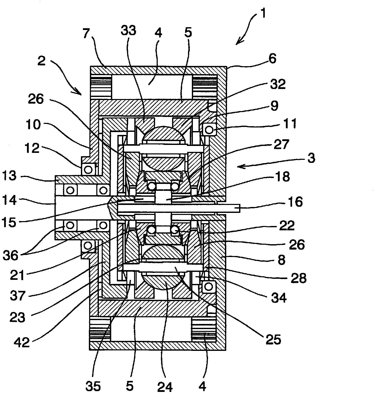
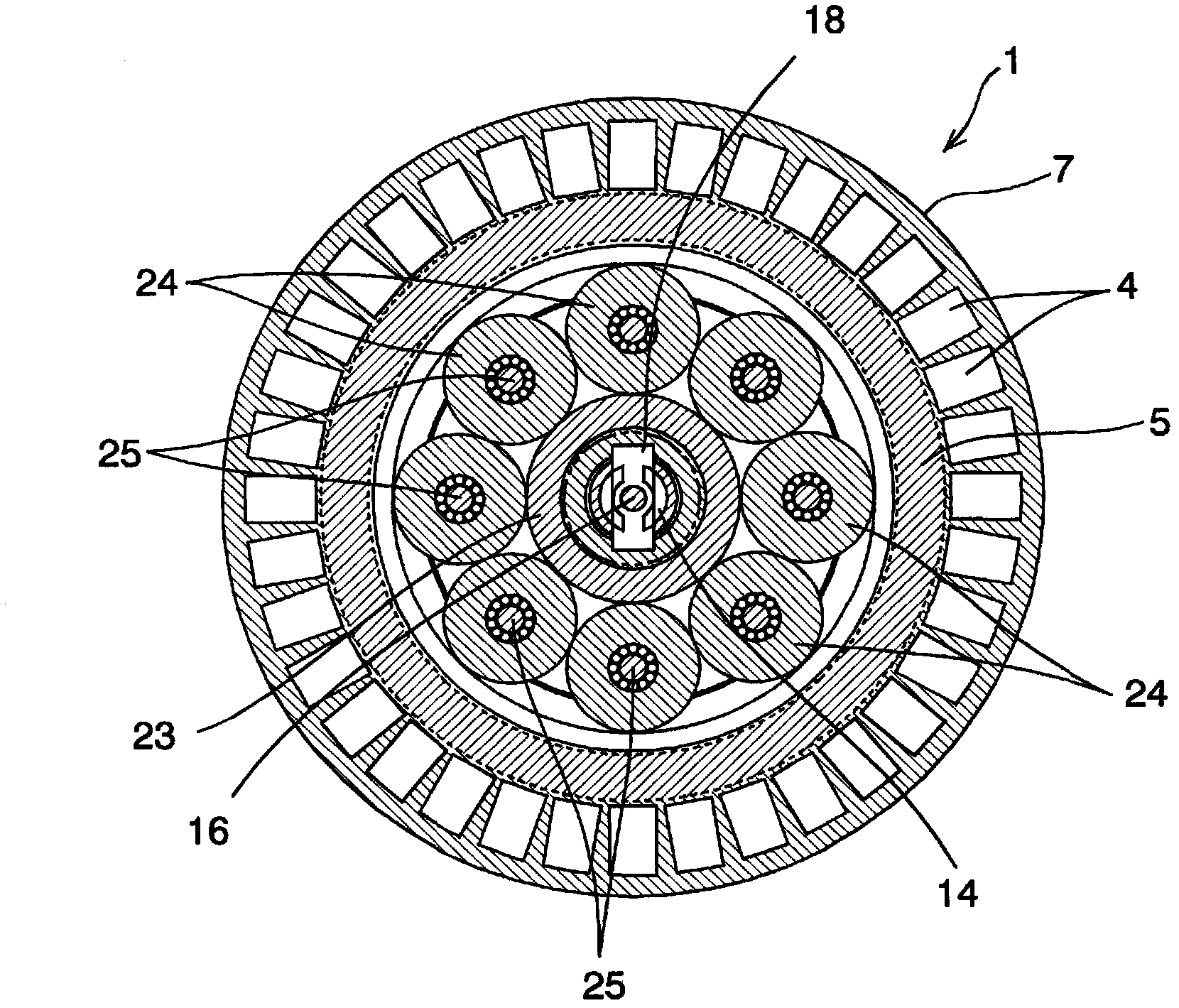
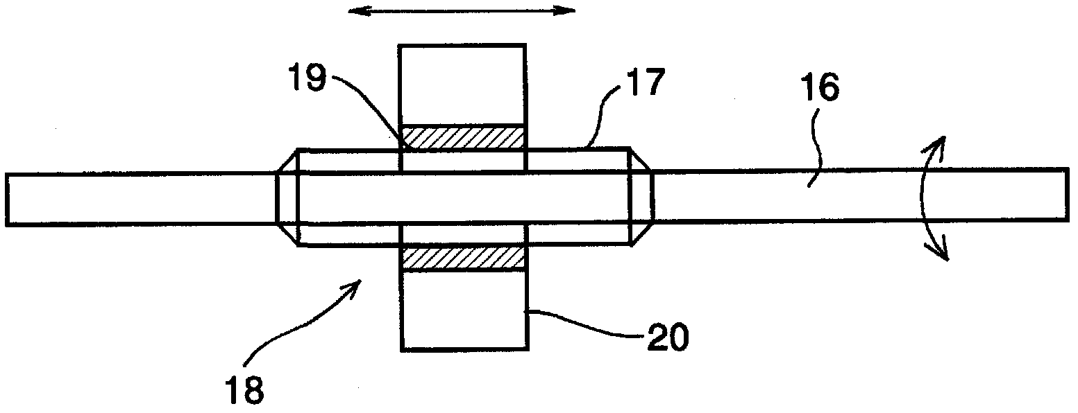
[0035] Next, the present invention will be described more specifically. figure 1 and figure 2 This shows an example of the electric motor 1 according to the present invention, and the electric motor 1 shown here is configured such that the continuously variable transmission mechanism 3 is disposed on the inner peripheral portion of the electric motor unit 2 . When describing the structure of the motor unit 2 , the motor unit 2 includes a stator coil 4 and a rotor 5 disposed on the inner peripheral side of the stator coil 4 . The stator coil 4 is configured by arranging a plurality of coils wound around an iron core in a cylindrical shape, and is fixed to the inner peripheral surface of the cylindrical portion 7 of the outer casing 6 . The outer casing 6 is a cylindrical member having a bottom, and the plate-shaped portion opposite to the bottom is an end plate portion 8 , and the cylindrical portion 7 is integrated with the outer peripheral portion of the disk-shaped end pla...


PUM


Abstract

A motor drivable with improved energy efficiency and generally reduced in size. The motor (1) with a transmission function in which the rotational speed of a rotor (5) is differentiated from the rotational speed of an output shaft (13) for outputting a torque transmitted from the rotor (5) thereto comprises a stator coil (4) attached to the inner peripheral surface of a cylindrical outer case (6), the cylindrical rotor (5) which is disposed on the inner peripheral side of the stator coil (4) and which generates a torque by receiving the magnetism generated by the stator coil (4), and a continuously variable transmission mechanism (3) which is disposed on the inner peripheral side of the rotor (5)and which steplessly varies the ratio of the rotational speed of an input member (32) connected to the rotor (5) to the rotational speed of an output member (33); rotated by receiving a torque from the input member (32) and connected to the output shaft (13).

Description

technical field [0001] The present invention relates to an electric motor with a variable speed function capable of changing the ratio of the rotational speeds of a rotor and an output shaft. Background technique [0002] The output characteristics of the motor vary depending on the structure, type, etc. of the motor, and there are various demands on the motor for this. Therefore, for example, although the requirements for the output characteristics are satisfied, the requirements for the structure are not satisfied. Therefore, a motor has been developed in the past. The electric mechanism is such that the speed change mechanism is housed inside the outer casing in which the stator and the rotor are built. The torque of the rotor is increased or decreased according to the gear ratio and output from the output shaft. [0003] For example, Japanese Patent Application Laid-Open No. 2007-269129 discloses a wheel rotation device in which a stator is disposed on a concentric circ...

Claims


Application Information

Patent Timeline
Patent Type & Authority Applications(China)
IPC IPC(8): H02K7/10B60K7/00F16H15/52
CPCF16H15/06B60K7/0007B60K2007/0092F16H3/724H02K7/10F16H3/725B60K17/043B60K2007/0038H02K7/116F16H15/28
Inventor 小川裕之友松大辅村上新
Owner TOYOTA JIDOSHA KK
Learn More