
ultrasonic transducer

An ultrasonic transducer and ultrasonic vibration technology, applied in ultrasonic/sonic/infrasonic diagnosis, ultrasonic diagnosis, infrasonic diagnosis, etc., can solve the deformation of the rear mass block, affect the stress distribution of the crystal pile, and the stress distribution of piezoelectric elements and electrodes. Uniformity and other issues to achieve large compression range, improve efficiency, and reduce heat

Active Publication Date: 2014-10-01
REACH SURGICAL
View PDF9 Cites 0 Cited by
  • Summary
  • Abstract
  • Description
  • Claims
  • Application Information

AI Technical Summary

Problems solved by technology

[0008] The purpose of the present invention is to solve the defect of uneven stress distribution in the piezoelectric element and electrode of the ultrasonic transducer in the prior art, especially to avoid deformation due to the asymmetry of the rear mass block, thereby affecting the stress distribution in the crystal pile Uniformity of

Method used


Image

  • ultrasonic transducer
  • ultrasonic transducer
  • ultrasonic transducer

Examples


Embodiment Construction

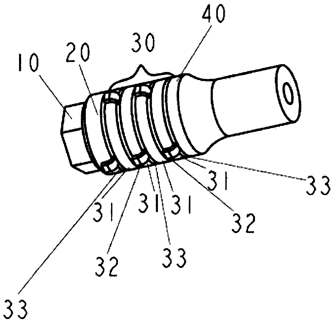
[0048] The present invention will be described in further detail below in conjunction with the accompanying drawings and specific embodiments. The specific embodiments described here are only used to explain the present invention, and are not used to limit the protection scope of the present invention.

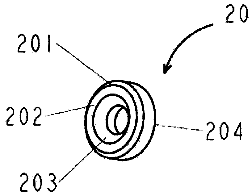
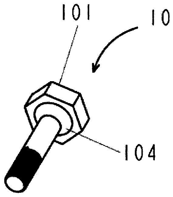
[0049] refer to image 3 A schematic diagram of an ultrasound transducer according to a specific embodiment of the invention is shown. The ultrasonic transducer of the present invention comprises: installation device 4, and installation device 4 is connected with a compressing device; Connection mode can be screw connection, also can adopt other connection modes such as spring connection, welding to replace; Crystal stack 3, be arranged on Between the installation device 4 and the compression device, the crystal stack 3 includes a plurality of electrodes stacked alternately with positive and negative electrodes, and a piezoelectric element 31 is arranged between two adjacent ...


PUM


Abstract

The invention discloses an ultrasonic transducer, comprising an installing device, a crystal stack and a rear mass block, wherein the installing device is connected with a compression device; the crystal stack is arranged between the installing device and the compression device; and the rear mass block is arranged between the crystal stack and the compression device. The ultrasonic transducer is characterized in that both the contact end surface of the crystal stack and the contact end surface of the compression device are planes and are same in shape and size; the compression device is provided with a contact surface of the rear mass block contacted with the rear mass block; the contact surface of the rear mass block is centrosymmetric to the geometric center of the contact end surface of the compression device; and the area of the contact surface of the rear mass block is less than that of the contact end surface of the compression device. In the ultrasonic transducer, by improvement on the symmetry of the rear mass block, the uniformity of stress distribution in the ultrasonic transducer is improved, so that the efficiency of the ultrasonic transducer is improved.

Description

technical field [0001] The present invention generally relates to ultrasonic transducers and their applications, in particular sandwich-type ultrasonic transducers with compression means and their applications. Background technique [0002] In the prior art, ultrasonic emitting devices have various applications, such as for surgical treatment. Ultrasound transmitting devices typically include transducers that convert electrical energy into vibrations at ultrasound frequencies, which are transmitted to vibrate the tip of the surgical instrument. [0003] A sandwich-type high-efficiency ultrasonic transducer usually includes a mounting device and a rear mass, and a crystal stack is arranged between the mounting device and the rear mass, and the crystal stack is an alternate stack of piezoelectric elements and electrodes. Most of these high-efficiency ultrasonic transducers are pre-compressed, using compression bolts extending axially through the die stack to apply the compres...

Claims


Application Information

Patent Timeline
Patent Type & Authority Patents(China)
IPC IPC(8): A61B8/00A61B17/00
Inventor 方云才钟学平陈启章梁耀汪炬杨晓峰姚银锋
Owner REACH SURGICAL
Learn More