Liquid spray head and ink-jet recording device
A liquid ejection head and liquid technology, which is applied in the field of liquid interference between nozzles, can solve problems such as crosstalk and ejection instability, and achieve the effects of reducing crosstalk, suppressing crosstalk and suppressing vibration.
- Summary
- Abstract
- Description
- Claims
- Application Information
AI Technical Summary
Problems solved by technology
Method used
Image
Examples
Deformed example 1
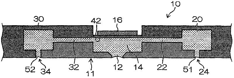
[0078] exist figure 2 In , an example is shown in which one air-opening hole (24, 34) is formed with respect to one common flow path (20, 30), but the number of air-opening holes and the distribution (arrangement method) of the arrangement can be various. design.
[0079] For example, in figure 2 In the flow path resistance value from the connection port 26 on the supply side (corresponding to the "first connection port") to the pressure chamber 14 (from the connection port 26 through the first common flow path 20, the first independent flow path 22 to the pressure The flow path resistance value of the flow path system of the chamber 14), and the flow path resistance value from the connection port 36 (corresponding to the "second connection port") on the recovery side to the pressure chamber 14 (from the connection port 36 via the second common flow 30, the second independent flow path 32 to the pressure chamber 14 (the flow path resistance value of the flow path system of...
Deformed example 2
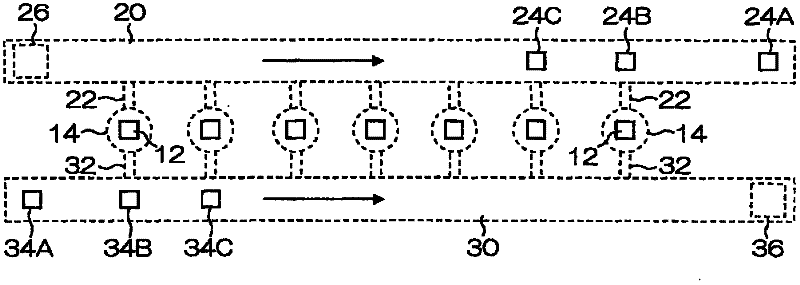
[0082] image 3 It is a figure which shows another modification. exist image 3 in, for and in figure 1 and figure 2 Elements having the same or similar structures as described in hereinafter are denoted by the same reference numerals, and descriptions thereof are omitted.
[0083] Such as image 3 As shown, a plurality of atmospheric opening holes ( 24A to 24C, 34A to 34C) may be arranged with respect to one common flow path ( 20 , 30 ). In this figure, atmosphere opening holes 24A, 24B, and 24C are respectively formed in the vicinity of the end portion (right end portion) of the first common flow path 20 and the two nozzles 12 near the end portion. The same is true for the second common flow path 30. The atmosphere opening holes 34A, 34B, 34C.
[0084] exist image 3 Among them, the atmosphere opening holes (24B, 24C, 34B, 34C) are arranged near the branch point from the common flow path (20, 30) to the independent flow path (22, 32), but the atmosphere opening hole...
Deformed example 3
[0088] exist Figure 1 to Figure 3 In , the circulation type inkjet head that circulates the ink in the pressure chamber 14 is described, but the present invention can also be applied to a non-circulation type inkjet head that does not have a flow path of a circulation system (recovery system). exist Figure 4 An example of arrangement of nozzles and air-opening holes in a non-circulation type inkjet head is shown in . exist Figure 4 in, for and in image 3 The same or similar structures in the examples described in hereinafter are denoted by the same reference numerals, and descriptions thereof are omitted.
[0089]
[0090] (Conditions of inertia)
[0091] Assuming that the respective inertias (inertance) of the nozzle for ink ejection, the throttle portion, and the air opening hole are La, Lb, and Lc, Lb>La and Lb>Lc are preferable.
[0092] The inertia L is represented by the following formula (Equation 1), where p is the density of the ink, l is the length of the ...
PUM
 Abstract
Description
Claims
Application Information
 - R&D
- Intellectual Property
- Life Sciences
- Materials
- Tech Scout
- Unparalleled Data Quality
- Higher Quality Content
- 60% Fewer Hallucinations
Browse by: Latest US Patents, China's latest patents, Technical Efficacy Thesaurus, Application Domain, Technology Topic, Popular Technical Reports.
© 2025 PatSnap. All rights reserved.Legal|Privacy policy|Modern Slavery Act Transparency Statement|Sitemap|About US| Contact US: help@patsnap.com


