Cleaning working chamber and cleanness monitoring system

A monitoring system and studio technology, applied in the field of purification equipment, can solve the problems that the operator does not know the clean condition of the work area and cannot monitor the working condition of the clean studio, etc., and achieves the effect of remote online monitoring.

Active Publication Date: 2012-01-11
SUZHOU INDAL PARK HJCLEAN TECH
View PDF5 Cites 10 Cited by
  • Summary
  • Abstract
  • Description
  • Claims
  • Application Information

AI Technical Summary

Problems solved by technology

[0004] However, when the currently used clean studio is working, the operator often does not know the cleanliness of the work area, and can only test its working performance by regularly using related testing equipment, such as dust particle counters, etc., and cannot check the cleanliness of the clean studio. real-time monitoring of working conditions

Method used


Image

  • Cleaning working chamber and cleanness monitoring system
  • Cleaning working chamber and cleanness monitoring system
  • Cleaning working chamber and cleanness monitoring system

Examples


Embodiment 1

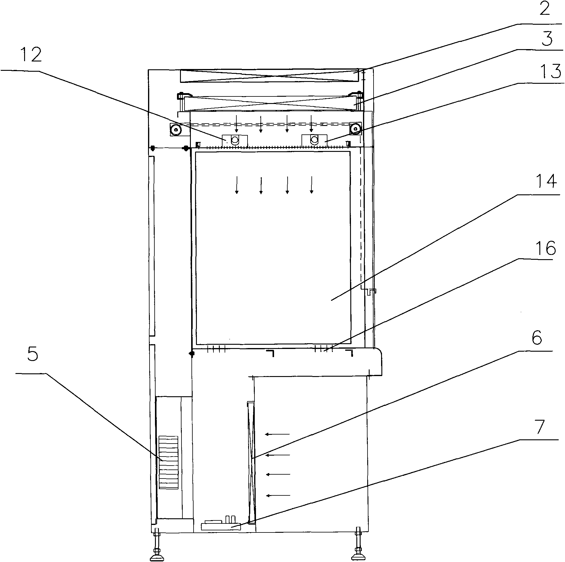
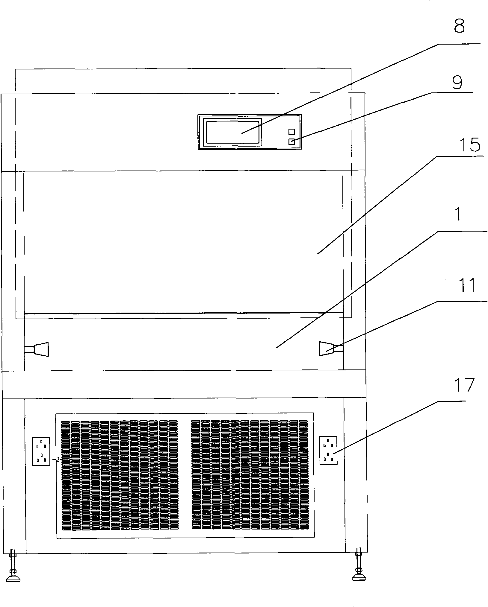
[0022] see figure 1 , figure 2 , a kind of clean working room provided by the present invention comprises upper, middle and lower levels, the middle level is the working area 1, and the top of the upper level is provided with an exhaust air filter 2, and the air supply filter 3 is located above the working area 1, and is connected with the exhaust air The wind filter 2 forms a cavity.

[0023] A laser dust particle transmitter 11 is installed in the working area to detect the size and concentration of dust particles in the working area 1. The installation location can be located on both sides of the working area 1, or above or below the working area. , the number of installations is not limited to one, but can also be two or more. An illuminating lamp 12 and an ultraviolet lamp 13 are also arranged above the working area 1 for illuminating and disinfecting the working area. Toughened glass 14 is arranged on both sides of the working area 1, and a toughened glass sliding do...

Embodiment 2

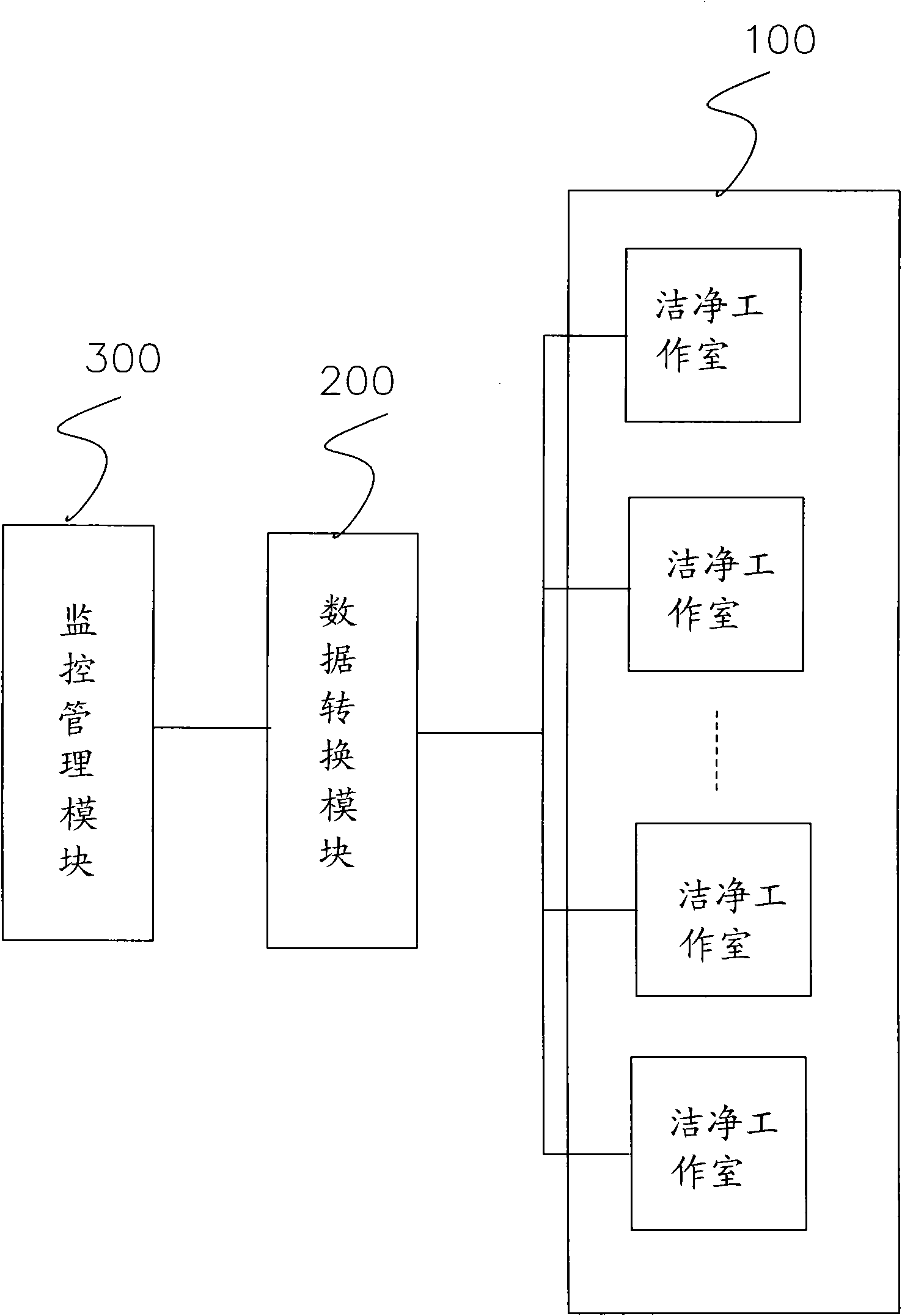
[0029] The present invention also proposes a cleanliness monitoring system, see image 3 As shown in the schematic structural diagram of the system, the system includes one or more clean studios 100 disclosed in the first embodiment, a data conversion module 200 and a monitoring and management module 300 . The monitoring and management module 300 is specifically a computer system, which can transmit the detection results of each clean studio to the computer system for control and management through the data conversion module 200, and can realize online remote monitoring of one or more clean studios.

[0030] In other embodiments of the present invention, a printing module 400 is also included, see Figure 4 , when it is necessary to count the cleanliness test results of some or all working rooms at a certain time or at a certain temperature, the data form can be called out through the computer system and printed through the printing module 400 .

[0031] In the present invent...


PUM


Abstract

The invention discloses a cleaning working chamber and a cleanness monitoring system. The cleaning working chamber comprises a cleaning mechanism and a working area, wherein the cleaning mechanism comprises a blowing-in device and a filter device, and the cleaning mechanism is also connected with a detection device which is used for detecting the cleanness of the working area. By the invention, the size and density of the dust particles in the working area can be detected in real time, the real-time state can be transmitted to a remote computer to be monitored, and thus, the remote on-online monitoring of the cleaning working chamber can be realized.

Description

technical field [0001] The invention relates to a purification device, in particular to a clean room and a cleanliness monitoring system. Background technique [0002] Purification equipment has been widely used in various fields such as biopharmaceuticals, medical and health care, microelectronics and optics. Through purification equipment, the production, processing, storage and transportation of its products can be realized. [0003] The clean room is a kind of clean equipment used to store or transport the products to be protected. It is equipped with a circulating filtration system inside, so that the working area of ​​the clean room can maintain a certain degree of purity. [0004] However, when the currently used clean studio is working, the operator often does not know the cleanliness of the work area, and can only test its working performance by regularly using related testing equipment, such as dust particle counters, etc., and cannot check the cleanliness of the c...

Claims


Application Information

Patent Timeline
Patent Type & Authority Applications(China)
IPC IPC(8): B65D81/18G01N15/02G01N15/06B08B17/00
Inventor 曾世清
Owner SUZHOU INDAL PARK HJCLEAN TECH
Why Eureka
Try Eureka