Vehicle electromagnetic pulse effect multi-dimensional remote online monitoring system
An electromagnetic pulse, multi-dimensional technology, applied in closed-circuit television systems, selection devices of multiplexing systems, transmission systems, etc., can solve problems such as difficult comprehensive real-time monitoring of the running status of the test vehicle, strong electromagnetic interference of monitoring equipment, etc. Achieve low cost, strong electromagnetic interference resistance, and strong scalability
- Summary
- Abstract
- Description
- Claims
- Application Information
AI Technical Summary
Problems solved by technology
Method used
Image
Examples
Embodiment 1
[0016] Embodiment 1 Overall structure of the present invention
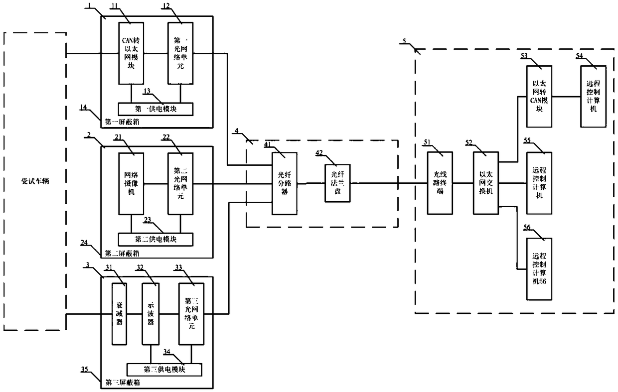
[0017] refer to figure 1 , the vehicle electromagnetic pulse effect multi-dimensional remote online monitoring system according to the present invention has a CAN bus diagnosis subsystem 1, an audio and video monitoring subsystem 2, an induced voltage measurement subsystem 3, an optical fiber distribution network 4 and a remote control subsystem 5. Among them, the remote control subsystem 5 is respectively connected to the CAN bus diagnosis subsystem 1, the audio and video monitoring subsystem 2 and the induced voltage measurement subsystem 3 through the optical fiber distribution network 4;
[0018]The CAN bus diagnostic subsystem 1 is composed of a CAN-to-Ethernet module 11, a first optical network unit 12, a first power supply module 13 and a first shielding box 14, and is used to monitor the vehicle electronic control during the electromagnetic pulse effect test. The CAN bus data of the system running state;...
Embodiment 2
[0023] Embodiment 2 Configuration steps of the present invention
[0024] Step 1: Configure the network management IP addresses of the network camera 21 in the CAN bus diagnosis subsystem 1 and the oscilloscope 33 in the induced voltage measurement subsystem 3 respectively;
[0025] Step 2: Perform the first optical network unit 12 on the optical line terminal 51 in the remote control subsystem 5, the second optical network unit 22 in the audio and video monitoring subsystem 2, and the third optical network unit 33 in the induced voltage measurement subsystem 3 register;
[0026] Step 3: configure the network management IP address of the optical line terminal 51 in the remote control subsystem 5;
[0027] Step 4: Configure the network management IP addresses of the first optical network unit 12 in the CAN bus diagnosis subsystem 1, the second optical network unit 22 in the audio and video monitoring subsystem 2, and the third optical network unit 33 in the induced voltage mea...
Embodiment 3
[0031] Embodiment 3 Working principle of the present invention
[0032] The CAN-to-Ethernet module 11 in the CAN bus diagnostic subsystem 1 converts the CAN bus data packets reflecting the operating status of the electronic control system of the vehicle into Ethernet data packets. The remote control computer 54 sends the vehicle electronic control system CAN bus data monitored by the CAN bus diagnostic subsystem 1, and on the other hand receives the remote control command sent by the first remote control computer 54 in the remote control subsystem 5. The first power supply module 13 is CAN The Ethernet-to-Ethernet module 11 and the first optical network unit 12 provide independent power supply, and the CAN-to-Ethernet module 11 , the first optical network unit 12 and the first power supply module 13 are placed inside the first shielding box 14 .
[0033] The network camera 21 in the audio and video monitoring subsystem 2 collects video signals reflecting the running state of t...
PUM
 Abstract
Description
Claims
Application Information
 - R&D
- Intellectual Property
- Life Sciences
- Materials
- Tech Scout
- Unparalleled Data Quality
- Higher Quality Content
- 60% Fewer Hallucinations
Browse by: Latest US Patents, China's latest patents, Technical Efficacy Thesaurus, Application Domain, Technology Topic, Popular Technical Reports.
© 2025 PatSnap. All rights reserved.Legal|Privacy policy|Modern Slavery Act Transparency Statement|Sitemap|About US| Contact US: help@patsnap.com

