Method and device for realizing multicast service in Internet protocol (IP) network

An IP network and multicast technology, applied in the field of network communication, can solve the problems of wasted bandwidth, limited bandwidth, line congestion, etc., and achieve the effect of saving line bandwidth

Inactive Publication Date: 2012-01-11
NEW H3C TECH CO LTD
View PDF4 Cites 13 Cited by
  • Summary
  • Abstract
  • Description
  • Claims
  • Application Information

AI Technical Summary

Problems solved by technology

This phenomenon will waste bandwidth, even line congestion and other situations. For example, the rent of ISP lines is usually very expensive. Therefore, the bandwidth of ISP lines rented by the IP surveillance system is usually very limited, such as 2M bandwidth. In this way, the sum of the traffic of all multicast sources is often greater than the bandwidth of the ISP line. Therefore, it is necessary to implement the multicast on-demand function and avoid receiving multicast streams ordered by other multicast receivers. Multicast streaming to self-demand

Method used


Image

  • Method and device for realizing multicast service in Internet protocol (IP) network
  • Method and device for realizing multicast service in Internet protocol (IP) network
  • Method and device for realizing multicast service in Internet protocol (IP) network

Examples


Embodiment 1

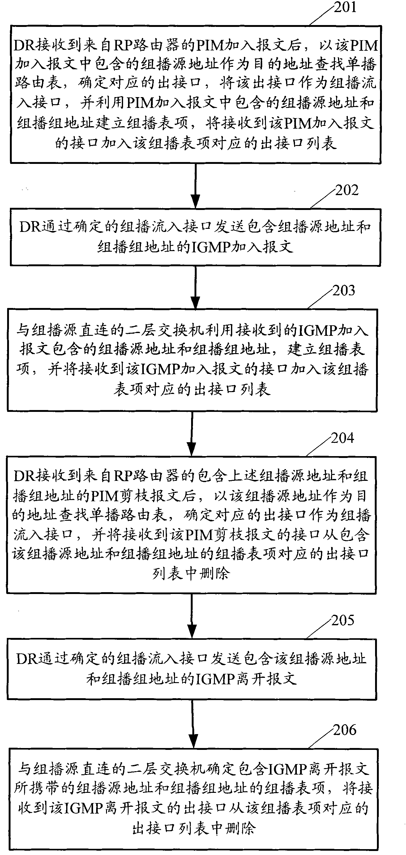
[0027] Embodiment 1, the situation in the PIM SSM mode. figure 2 The detailed method flowchart provided for Embodiment 1 of the present invention, such as figure 2 As shown, the following steps may be specifically included:

[0028] Step 201: After the DR receives the PIM join message from the downstream router, it searches the unicast routing table with the multicast source address contained in the PIM join message as the destination address, determines the corresponding outbound interface, and sets the outbound interface as the group broadcast the incoming interface, and use the multicast source address and multicast group address contained in the PIM join message to establish a multicast entry, and add the interface that received the PIM join message to the corresponding outbound interface list of the multicast entry.

[0029] In PIM SSM mode, the IGMP join message sent by the multicast receiver will contain both the multicast source address and the multicast group addre...

Embodiment 2

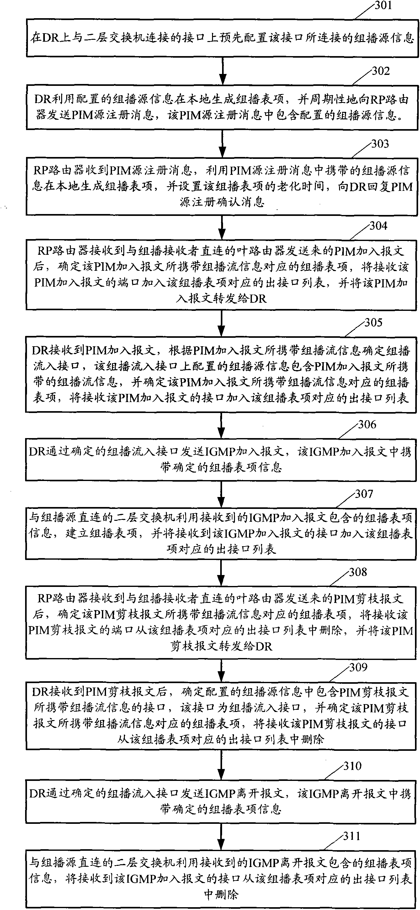
[0049] Embodiment 2, the situation in the PIM SM mode. image 3 The detailed method flowchart provided for the second embodiment of the present invention, such as image 3 As shown, the following steps may be specifically included:

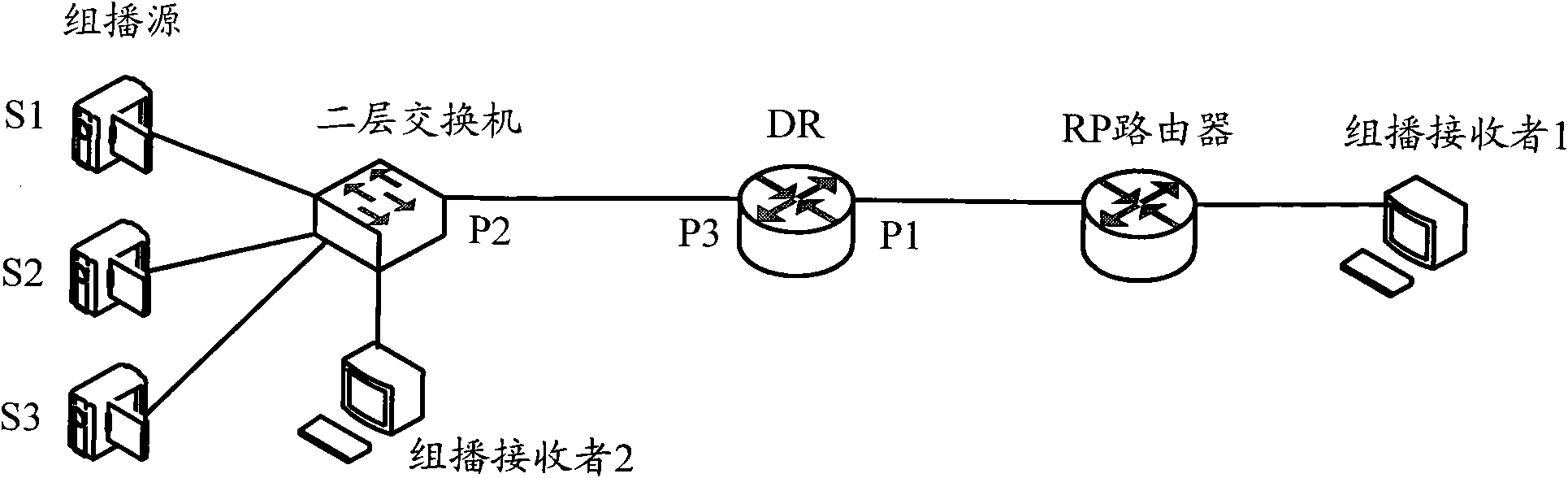
[0050] Step 301: Pre-configure the information of the multicast source connected to the interface on the interface connected to the Layer 2 switch (the Layer 2 switch on the multicast source side directly connected to the DR) on the DR.

[0051] In the PIM SM mode, the IGMP join message sent by the multicast receiver only contains the multicast group address, when the DR receives the IGMP join message, it cannot use the multicast source address to search the unicast routing table. Multicast incoming interface, in view of this problem, in this embodiment, the interface (such as figure 2 Configure the multicast source information associated with the interface on the P3 interface in .

[0052] Wherein, the configured multicast source information ...


PUM


Abstract

The invention provides a method and a device for realizing a multicast on-demand service in an Internet protocol (IP) network. A designated router (DR) does not transmit a protocol independent multicast (PIM) Hello message and a multicast discovery protocol query message to a multicast source side layer 2 switch directly connected with the DR. The method comprises that: after receiving a PIM addition message from a downstream router, the DR determines a multicast stream input interface corresponding to multicast stream information carried by the PIM addition message, and adds an interface receiving the PIM addition message into an output interface list of a multicast table entry corresponding to the multicast stream information; and the DR transmits the multicast discovery protocol addition message to the layer 2 switch by the determined multicast stream input interface, wherein the multicast discovery protocol addition message carries the information of the multicast table entry. By the method and the device, a multicast on-demand function can be realized in the IP network, and a line bandwidth between the multicast source side layer 2 switch directly connected with the DR and the DR can be saved.

Description

technical field [0001] The present invention relates to network communication technology, in particular to a method and device for realizing multicast service in IP network. Background technique [0002] IP multicast technology effectively solves the problem of single-point transmission and multi-point reception, and realizes efficient point-to-multipoint data transmission in the IP network, which can greatly save network bandwidth and reduce network load. Taking advantage of the multicast feature of the network, some new value-added services, including Internet information services such as online live broadcast, Internet TV, distance education, telemedicine, Internet radio, and real-time video conferencing, have developed rapidly. [0003] With the rapid development of IP surveillance system, the application of multicast technology is getting more and more in-depth. It is also required to install cameras in various remote areas to maintain local security. Since the cost of ...

Claims


Application Information

Patent Timeline
Patent Type & Authority Applications(China)
IPC IPC(8): H04L29/06H04L12/18H04L12/56H04L45/16
Inventor 周迪王晓东史扬刘宇
Owner NEW H3C TECH CO LTD
Why Eureka
Try Eureka