Three-shelled steam turbine

A technology for turbines, steam chambers, applied in mechanical equipment, engine components, machines/engines, etc., to solve problems such as valve diffuser effects

Inactive Publication Date: 2012-01-11
SIEMENS AG
View PDF5 Cites 6 Cited by
  • Summary
  • Abstract
  • Description
  • Claims
  • Application Information

AI Technical Summary

Problems solved by technology

The outer inner shell is also subject to thermal movements due to thermal changes, which can possibly influence the valve diffuser in a disruptive manner

Method used


Image

  • Three-shelled steam turbine
  • Three-shelled steam turbine
  • Three-shelled steam turbine

Examples


Embodiment Construction

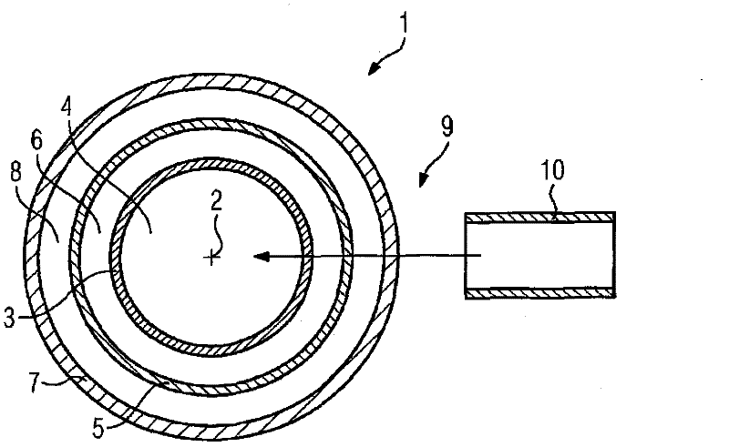
[0027] figure 1 A three-shell steam turbine as an embodiment of the turbine 1 is shown. The turbine 1 includes a rotor, not shown in detail, which is mounted to be rotatable about a rotation axis 2.

[0028] In this case, the axis of rotation 2 is perpendicular to the plane of the drawing. An inner inner shell 3 is provided around the rotor. A flow channel is formed between the inner inner shell 3 and the rotor, and hot steam exists in the steam chamber 4 in the flow channel. The steam present in the steam chamber 4 is live steam which can also be called hot steam. An outer inner shell 5 is provided around the inner inner shell 3. A first steam chamber 6 is formed between the outer inner shell 5 and the inner inner shell 3. The first steam chamber 6 usually contains waste steam, which flows from the inner inner shell 3 to the flow channel and to the final stage, and is distributed around the inner inner shell 3 and thus cools the inner inner shell 3.

[0029] The inner shell 5...


PUM


Abstract

The invention relates to a three-shelled turbo machine (1) having a valve (10), wherein the valve (10) is coupled to the three-shelled turbo machine (1) via two sealing arrangements (12, 20) and by means of an intermediate ring (18) in a sealing manner.

Description

Technical field [0001] The present invention relates to a turbomachine with a valve, wherein the turbomachine includes an inner inner shell, an outer inner shell, and an outer shell, wherein the valve includes a valve diffuser, wherein the valve diffuser is arranged on the inner inner shell, and the valve diffuser A first sealing element is arranged between the compressor and the inner inner shell, wherein the valve diffuser has a flange, and the flange is connected with the outer shell. Background technique [0002] Turbine is understood to mean, for example, steam turbine. Steam turbines generally have a rotatably mounted rotor and a casing arranged around the rotor. A flow channel is formed between the rotor and the inner shell. The shell in the steam turbine must be able to fulfill multiple functions. First, the guide vanes are arranged on the casing and in the flow channel, and secondly, the inner casing must withstand the pressure and temperature of the flowing medium fo...

Claims


Application Information

Patent Timeline
Patent Type & Authority Applications(China)
IPC IPC(8): F01D9/06F01D25/26
CPCF01D9/06F01D25/26
Inventor 海因茨・达林格本亚明・克洛斯-格罗特乌韦・赞德
Owner SIEMENS AG
Why Eureka
Try Eureka