Focus positioning treatment device and system thereof

A technology for a treatment device and a positioning component, which is applied in the directions of treatment and ultrasonic therapy, can solve the problems of bone blocking, low positioning accuracy, and inaccurate positioning and focusing, and achieves the effects of reducing damage, saving energy, and improving medical effects.

Active Publication Date: 2012-01-18
SHENZHEN HUIKANG PRECISION APP
View PDF4 Cites 0 Cited by
  • Summary
  • Abstract
  • Description
  • Claims
  • Application Information

AI Technical Summary

Problems solved by technology

[0002] The lesion locating device is a medical device, which is used very frequently in reality. It is used to locate the lesion inside the human body for further treatment. The current lesion locating device mainly adjusts the various components during use. , so as to realize the focusing and positioning of incident energy such as ultrasonic waves, and then realize the positioning of the adjustment lesion, but the positioning and focusing are not accurate enough through the adjustment method of each component, so the ultrasonic unit required by this existing positioning device Large area incident energy and low positioning accuracy affect the accuracy of lesion positioning. In addition, during the focused treatment of the lesion by the components, it is inevitable that they will be blocked by bones. Therefore, there may be damage to the lesion The dead angle problem of focused treatment makes it impossible to fully realize focused treatment of lesions

Method used


Image

  • Focus positioning treatment device and system thereof
  • Focus positioning treatment device and system thereof
  • Focus positioning treatment device and system thereof

Examples


Embodiment 1

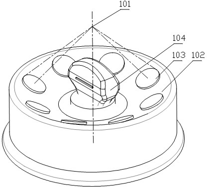
[0044] Such as figure 1 As shown, this example provides a focused positioning therapy device, including:

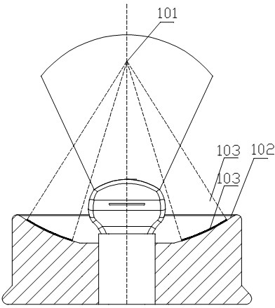
[0045] The first wave source assembly 102, the upper surface of which is a concave spherical member, the center of which is the focusing point 101;

[0046]The second wave source assembly 103 includes at least two wave source wafers installed on the concave spherical member and working independently, the wave source wafer and the concave spherical member have the same spherical center; and,

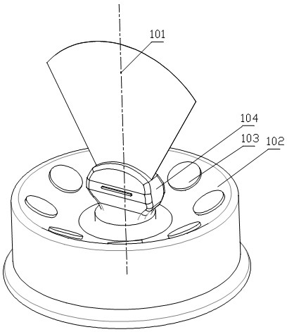
[0047] The positioning assembly 104 is installed at the center of the first wave source assembly 102, and its axis passes through the focus point 101. The positioning assembly 104 can rotate and move up and down relative to its axis.

[0048] Wherein, the upper surface of the first wave source assembly 102 is a concave spherical member, the concave spherical member is a concave spherical member, and the center of the concave spherical member is the focal point 101; the focal point 1...

Embodiment 2

[0057] Different from Embodiment 1, the wave source chip of the second wave source assembly 103 in this example is an ultrasonic chip, and the wave source emitting surface of the ultrasonic chip has the focal point 101 as the center of the sphere.

[0058] Wherein, the wave source chip adopts an ultrasonic chip, and the ultrasonic chip is a chip that emits ultrasonic waves. The emitted ultrasonic energy is used to focus on the position of the lesion to perform ultrasonic treatment on the lesion. It is a spherical surface at the center of the sphere, and the wave source emission surface is the side where the ultrasonic chip emits wave source energy. The emission surfaces of the ultrasonic chip are all spherical structures, and the spherical structure can adopt a concave spherical structure, and the focal point 101 is the center of the sphere , based on the location of the lesion, more precise focus therapy can be realized; the ultrasonic chip is installed on the concave spherica...

Embodiment 3

[0062] The difference from Embodiment 1 is that the positioning component 104 in this example uses a B-ultrasound probe, and the B-ultrasound probe uses rotation for tomographic scanning.

[0063] Wherein, the positioning member adopts a B-ultrasound probe, and the B-ultrasound probe can rotate around the axis of the focus positioning treatment device, and can also move up and down along its axis, and the B-ultrasound probe can perform tomographic scanning by rotating at different angles Determine the location of the lesion.

[0064] This example further adopts the above-mentioned technical features, and its advantage is that the upper surface of the first wave source assembly 102 is a concave spherical member, and the spherical center of the concave spherical member is the focal point 101, which is also the wave source chip. center of the sphere, so as to achieve precise focus therapy on the lesion. The second wave source assembly 103 includes at least two wave source chips i...


PUM


Abstract

The invention relates to a focus positioning treatment device and a system thereof. The focus positioning treatment device comprises a first wave source assembly 102, a second wave source assembly 103 and a positioning assembly 104, wherein the upper surface of the first wave source assembly 102 is a concave ball surface component, the ball center of the concave ball surface component is a focusing focus 101, the second wave source assembly 103 comprises at least two wave source wafers, the wave source wafers are arranged on the concave ball surface component and respectively and independently work, the wave source wafers and the concave ball surface component share one ball center, the positioning assembly 104 is arranged at the center position of the first wave source wafer 102, the axial line of the positioning assembly 104 passes through the focusing focus 101, the positioning assembly 104 can rotate relative to the axial line and can upwards and downwards move, the wave source wafers and the concave ball surface component share one ball center, and in addition, the ball center is the focusing focus 101, so the focus treatment on the basis of realizing the precise positioning on the focus position is realized, in addition, the second wave source assembly 103 comprises at least two wave source wafers, the wave source wafers respectively and independently work, and the blocking of bones on the wave source energy is convenient to avoid.

Description

technical field [0001] The invention relates to a focus positioning device, in particular to a focus positioning treatment device and a system thereof. Background technique [0002] The lesion locating device is a medical device, which is used very frequently in reality. It is used to locate the lesion inside the human body for further treatment. The current lesion locating device mainly adjusts the various components during use. , so as to realize the focusing and positioning of incident energy such as ultrasonic waves, and then realize the positioning of the adjustment lesion, but the positioning and focusing are not accurate enough through the adjustment method of each component, so the ultrasonic unit required by this existing positioning device Large area incident energy and low positioning accuracy affect the accuracy of lesion positioning. In addition, during the focused treatment of the lesion by the components, it is inevitable that they will be blocked by bones. Th...

Claims


Application Information

Patent Timeline
Patent Type & Authority Applications(China)
IPC IPC(8): A61N7/00
Inventor 陈明
Owner SHENZHEN HUIKANG PRECISION APP
Why Eureka
Try Eureka