Rotary cutting tool

A technology of cutting tools and knives, which is applied in the direction of rotary cutting tools, manufacturing tools, wood processing appliances, etc., can solve problems such as burrs on one side edge, cutting damage, and hindering the stability of being cut, so as to reduce prices, suppress burrs and Defect effect

Inactive Publication Date: 2012-01-18
昆山兼房高科技刀具有限公司
View PDF0 Cites 2 Cited by
  • Summary
  • Abstract
  • Description
  • Claims
  • Application Information

AI Technical Summary

Problems solved by technology

However, even with this device, although the problem of low bending rigidity is not as serious as the above-mentioned straight knife, it still exists, and the problem of longitudinal bending cannot be avoided when the knife is thin.
In addition, this device applies force in the transverse direction to the cut material at one end of the cutter, so especially when cutting directional fibrous wood, etc., burrs and cuts are likely to occur on one side of the edge. And other issues
In addition, due to the twisting design of this cutting device, force will be applied to one side of the material to be cut in the horizontal direction, so the material to be cut will be moved in the horizontal direction, hindering the stability of the cut

Method used


Image

  • Rotary cutting tool
  • Rotary cutting tool
  • Rotary cutting tool

Examples


no. 1 example

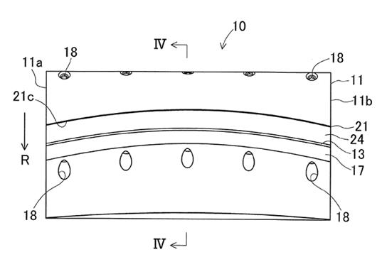
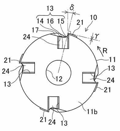
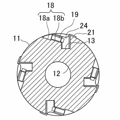
[0027] Such as Figure 1-6 As shown, the body 11 of the rotary cutting tool provided by the present invention is a metal cylinder, and is provided with a hole shaft 12 in the center, and four equidistant points on the outer edge of the cylindrical body 11 are provided with four holes of the same shape. The installation slot 13 is curved in an arc shape opposite to the rotation direction R of the main body 11 , and is symmetrical in the axial direction of the main body 11 . The front wall surface 14 and the rear wall surface 15 of the installation groove 13 are equal in length across, and the bottom wall surface 16 of the installation groove 13 is at right angles to the front wall surface 14 and the rear wall surface 15, and forms a parallel extending plane in the axial direction. After the cutter 21 described later, the inclination angle δ of the rear wall surface 15 relative to the radial direction is 15°, and increases with the bending of the mounting groove 13, and reaches ...

no. 2 example

[0035] Such as Figure 8-9 As shown, the installation groove 33 protrudes toward the direction of the rotation direction R on the outer circumference of the cylindrical body 31, and the bending direction of the metal pressing tool 37 is the same as Figure 5 The direction of bending is shown in the opposite direction.

[0036] In this embodiment, the tool 35 protrudes toward the direction of the rotation direction R of the body 31. The two ends of the blade of the tool 35 have a certain inclination angle relative to the axis of the body 31, and there is a positive angle with respect to the two ends of the body 31. , Negative torsion angle, same as above-mentioned embodiment 1. Therefore, the bending rigidity of the cutter 35 is even higher. Therefore, in Example 2, since the use of relatively expensive materials can be reduced, the price cost is greatly reduced compared to the previous blade with a thickness of 3 mm. Also, in this embodiment 2, the blade 35c has positive an...

no. 3 example

[0038] Such as Figure 10-13As shown, the cylindrical body 41 and the handle 42 are connected on the same axis. There are two symmetrical mounting grooves 43 and two mounting holes 47 on the outer periphery of the body 41 . The front wall surface 44 of the mounting groove 43 is curved in the front direction of the rotation direction R of the main body 41 , the rear wall surface 45 is curved in an arc shape in the opposite direction, and the bottom wall surface 46 forms a plane parallel to the axial direction. In the mounting groove 43, the metal pressing tool 55 on the side of the front wall 44 and the tool pressing tool 61 next to the rear wall surface 45 are installed in the mounting groove 43, and the cutting tool 51 is sandwiched between the metal pressing tool 55 and the tool pressing tool 61.

[0039] The front side 55a of the metal presser 55 is flat with the front wall 44 , the back side 55b is curved outwards in a circular arc when it fits with the rear wall 45 , and...


PUM


Abstract

The invention provides a rotary cutting tool, which comprises a cylindrical body, a cutter and a metal press; mounting grooves of the same shape and the same number and mounting holes are formed at equal distance points of the outer edge of the cylindrical body, the mounting grooves are bent to arc relative to the body, and the mounting holes are positioned at the front sides of the front walls of the mounting grooves and penetrate the front walls of the mounting grooves; the front lateral surface of the metal press is provided with fixed holes corresponding to the mounting holes; the metal press is inserted into the mounting groove, and the cutter is inserted between the mounting groove and the metal press; and screws are inserted into the mounting holes and tightened, and the front ends of the screws are inserted into the fixed holes. The rotary cutting tool solves that the tool has high manufacturing cost and high cutting noise and burrs and cutting damage are easily produced and the like; simple and accurate installation of the cutter is realized; because the cutter has high bending rigidity, the noise during cutting is reduced; and burrs and cutting damage at two ends of a material can be effectively inhibited, and chips can be better removed.

Description

technical field [0001] The invention relates to a rotary cutting tool, in particular to a rotary cutting tool such as a four-sided planer, a planer, and a shaft-attached reamer equipped with plate-shaped blades. Background technique [0002] At present, rotary cutting tools are generally equipped with straight straight knives in parallel tool grooves on the axial direction of the outer surface of the planer tool. However, when a straight knife is installed, the cutting resistance is applied to the entire body of the knife while cutting, so there is a problem that the bending rigidity of the knife is small and the knife is prone to longitudinal bending. In order to avoid this problem, it is necessary to increase the thickness of the tool to ensure the bending rigidity of the tool. In that case, the amount of high-priced tool materials will be increased, and the cost of the tool will increase. In addition, in the case of a straight knife, there is another problem that the cu...

Claims


Application Information

Patent Timeline
IPC IPC(8): B23B27/16B27G13/04
Inventor 西尾悟井出强
Owner 昆山兼房高科技刀具有限公司
Why Eureka
Try Eureka