
Box body welding tracer

A profiling device and box technology, applied in welding equipment, auxiliary welding equipment, welding/cutting auxiliary equipment, etc., to achieve the effect of simple and compact structure, low manufacturing cost and convenient use

Active Publication Date: 2012-01-18
SHANDONG SHUIBO WELDING & CUTTING EQUIP MFG CO LTD
View PDF7 Cites 6 Cited by
  • Summary
  • Abstract
  • Description
  • Claims
  • Application Information

AI Technical Summary

Problems solved by technology

And welding without dead ends

Method used


Image

  • Box body welding tracer
  • Box body welding tracer
  • Box body welding tracer

Examples


Embodiment Construction

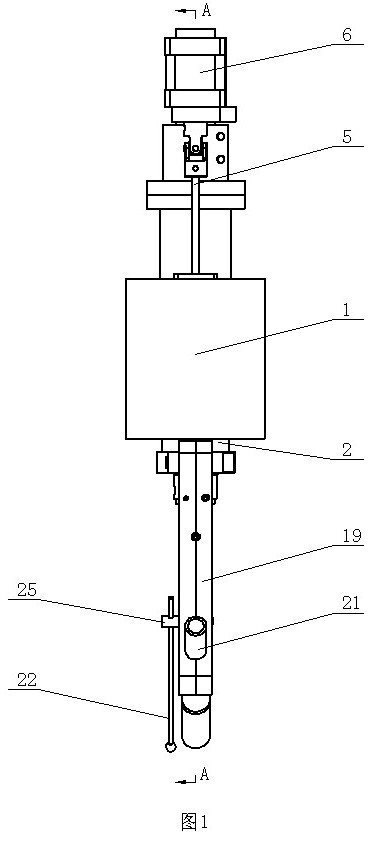
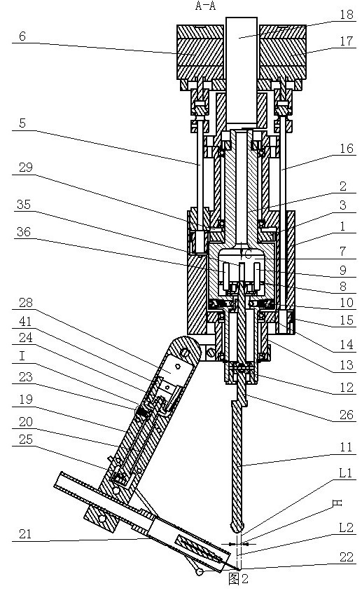
[0009] The box welding profiler of the present invention comprises an outer shell 1, a cavity 29 is provided in the outer shell 1, and an inner shell 2 is installed in the cavity 29, and the inner shell 2 can rotate relative to the outer shell 1. In order to reduce the rotational friction between the inner shell 2 and the outer shell 1, such as figure 2 As shown, a bearing is installed between the outer shell 1 and the inner shell 2. The inner shell rotating device is installed on the outer shell 1, and the execution part of the inner shell rotating device is connected with the inner shell 2 to provide power for the inner shell 2 to rotate relative to the outer shell 1. An inner cavity 7 is provided in the inner shell 2, and the first probe 9, the second probe 35 and the third probe 36 are fixedly installed in the inner cavity 7, and the first probe 9, the second probe 35 and the third probe 36 are not collinear. Such as figure 2 As shown, a universal joint is installed on...


PUM


Abstract

The invention discloses a box body welding tracer which comprises an outer shell. A cavity is formed in the outer shell; an inner shell is arranged in the cavity; an inner shell rotating device is arranged on the outer shell; an inner cavity is formed in the inner shell; three probes are fixedly arranged in the inner cavity; a universal joint is arranged on the inner shell; a swing bar is arranged on a swing part of the universal joint; an eccentric part is arranged at the lower part of the swing part or the swing bar of the universal joint; a workpiece contact part on the eccentric part is used as a contact part; a contact part central axis of the contact part is deviated by a certain distance H relative to a swing bar central axis of the swing bar; a plane on which the swing bar central axis and the contact part central axis are positioned is a horizontal plane; a plane vertical to the horizontal plane is a longitudinal plane; the intersecting line of the horizontal plane and the longitudinal plane is parallel to the swing bar central axis; the swing bar not only can swing along the horizontal plane, but also can swing along the longitudinal plane under the guide of the swing part of the universal joint; and the side wall of the inner shell is provided with two first regulators.

Description

technical field [0001] The invention relates to a box body welding profiler. Background technique [0002] It is difficult for existing welding machines to realize automatic profiling welding when welding boxes. seam welding, but cannot guide the welding torch to switch to another adjacent welding seam after welding one welding seam. In addition, because the existing profiling part and the profiling part in contact with the workpiece have a certain thickness, which is greater than the diameter of the welding wire, therefore, the welding torch cannot accurately weld the part near the intersection of the two weld seams, that is, the welding torch cannot completely weld a Weld seams, there are dead angles in welding. Therefore, the existing box body welding needs to manually control the welding torch, the welding precision is low, the welding efficiency is low, and the welding time is long. Contents of the invention [0003] The purpose of the present invention is to prov...

Claims


Application Information

Patent Timeline
Patent Type & Authority Applications(China)
IPC IPC(8): B23K37/00B23K37/02
Inventor 刘宪福
Owner SHANDONG SHUIBO WELDING & CUTTING EQUIP MFG CO LTD
Learn More