
Quantitative filling machine

A filling machine and filling head technology, applied in packaging, bottle filling, liquid bottling, etc., can solve the problems of short service life of parts, low equipment utilization rate, slow filling speed, etc., and achieve convenient disassembly and installation, and equipment The effect of high utilization rate and fast filling speed

Inactive Publication Date: 2012-01-18
LUZHOU HUIJIANG MACHINERY MFG
View PDF8 Cites 27 Cited by
  • Summary
  • Abstract
  • Description
  • Claims
  • Application Information

AI Technical Summary

Problems solved by technology

Therefore, the existing quantitative filling machines have the following problems: 1. Affected by the accuracy of the measuring cup, the flow state and foaming during liquid replenishment, the quantitative accuracy is low; 2. After a filling is completed, the measuring cup needs to be replenished with liquid , so the filling speed is slow; 3. Due to the lack of lubrication means, the ejector mechanism, filling valve, and liquid replenishment mechanism wear a lot, and maintenance needs to be carried out after filling a certain amount to avoid problems such as lax closing and jamming of the ejector rod. High maintenance cost and low utilization rate of equipment; 4. In order to avoid the influence of wear and corrosion on product quality, the service life of parts is short; The corresponding relationship between the height difference of the container bottle, the ejector mechanism and the container bottle is strictly required, so the maintenance and adjustment are cumbersome

Method used


Image

  • Quantitative filling machine
  • Quantitative filling machine

Examples


Embodiment Construction

[0016] The present invention will be further described below in conjunction with the accompanying drawings and embodiments.

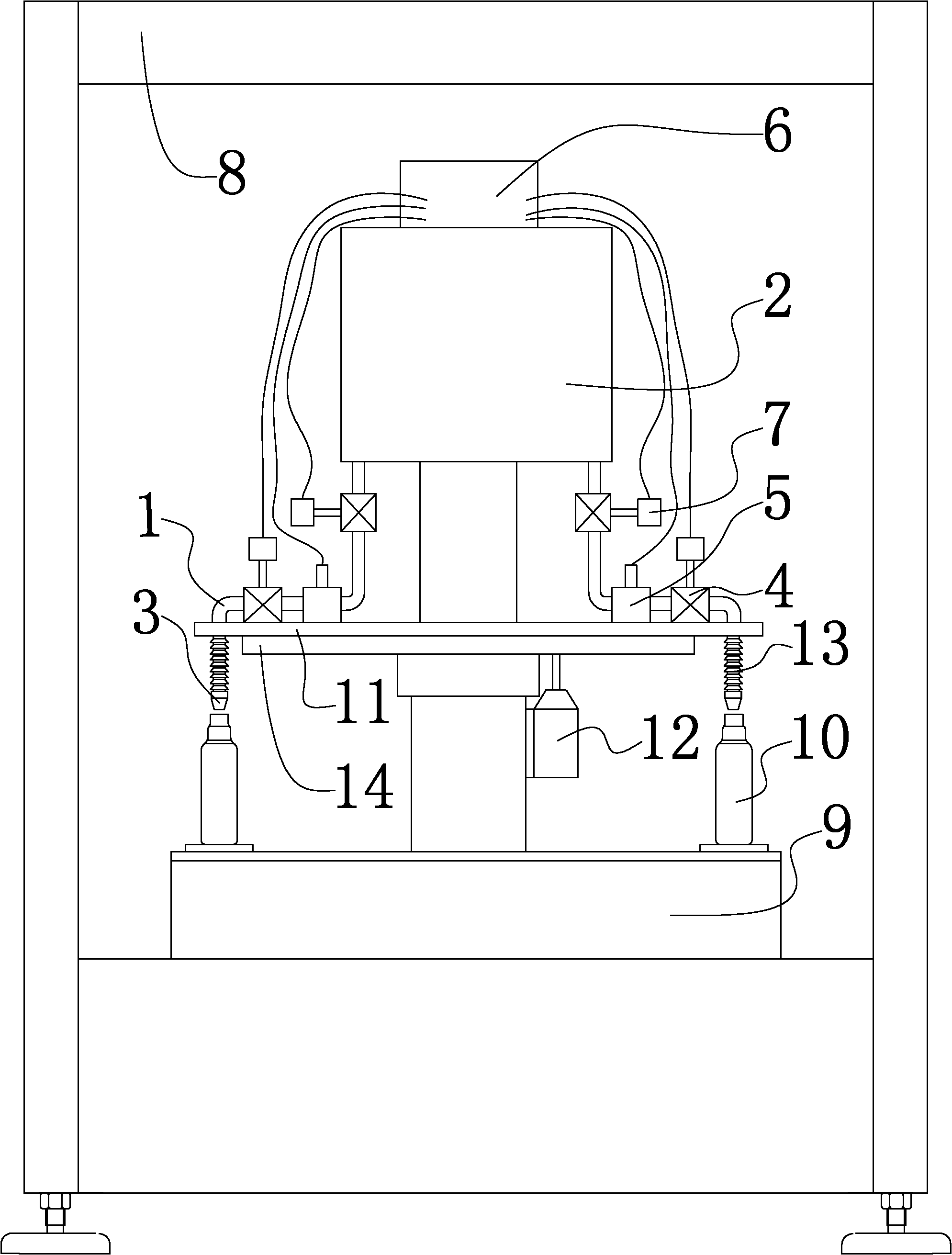
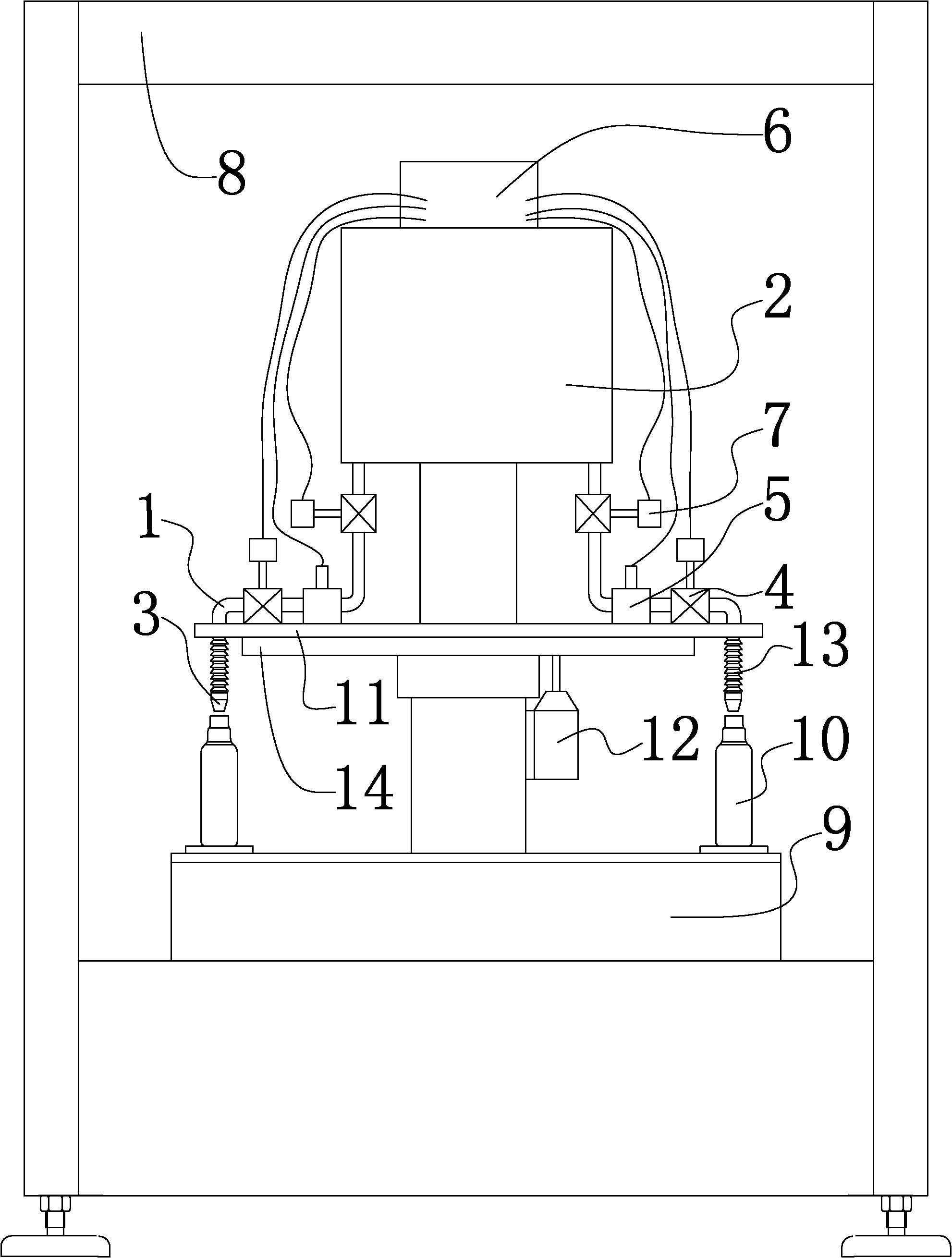
[0017] Such as figure 1 The quantitative filling machine shown includes a filling pipe 1, a liquid storage tank 2, a filling head 3, a transmission mechanism, and a frame 8. The filling pipe 1 is provided with an electronically controlled filling valve 4 and a flow meter 5 , a control system 6 connected with each electronically controlled filling valve 4 and a flow meter 5 is provided, and the filling head 3 and the liquid storage tank 2 are connected through the filling pipe 1 .

[0018] The liquid storage tank 2 is used to store the liquid to be filled. In the example shown in the figure, the existing automatic liquid replenishment liquid storage tank 2 that controls the liquid level through a buoy is used. The electronically controlled filling valve 4 is used to replace the existing mechanical filling valve to control the state of the filling pipe 1...


PUM


Abstract

The invention relates to a filling device, and especially relates to a quantitative filling machine for separate filling of liquid beverages and medicines; the filling machine comprises a filling tube, a liquid storage tank, a filling head, and a delivery mechanism; the filling tube is provided with electric-control filling valves, and flowmeters; a control system connected with each of the electric-control filling valves and flowmeters is disposed; the filling head is connected with the liquid storage tank through the filling tube. Present mechanical filling valves are substituted by the electric control filling valves; the filling amount is controlled by the control system according to monitoring signals of the flowmeters; and thus the quantification has high precision; When one filling is completed, no liquid supplement is required for a measuring cup, and thus the filling speed is high; no ejector pin mechanism, measuring cup and liquid-supplement mechanism thereof, or tray elevating mechanism is required to be disposed, and thus the structure is simple with less parts, and the machine is convenient for use and maintenance; the electric-control filling valves and flowmeters can be replaced directly; the machine is convenient for dismounting, and only has requirements for the corresponding relation of a container bottle and the filling head; therefore the maintenance, adjustment and calibration are simple, and the equipment utilization rate is high.

Description

technical field [0001] The invention relates to filling equipment, in particular to a quantitative filling machine for subpackaging liquid beverages and medicines. Background technique [0002] In the sub-packaging of liquid beverages and medicines, quantitative filling machines are required for filling. The existing quantitative filling machine is a mechanical structure, including a frame, a liquid storage tank, a liquid level control device for the liquid storage tank, a filling pipe, a filling head, a conveying device for a container bottle, and a tray installed on the conveying device. , Tray lifting mechanism, measuring cup, filling valve, ejector mechanism, etc. When working, the container bottle is placed on the tray, stepping along with the conveying device and corresponding to the filling head at each filling position, and then the container bottle rises with the tray under the action of the tray lifting mechanism and acts on the ejector mechanism through the bottl...

Claims


Application Information

Patent Timeline
IPC IPC(8): B67C3/28B67C3/26B67C3/24B67C3/22
Inventor 高泽林罗伟
Owner LUZHOU HUIJIANG MACHINERY MFG
Learn More