Shield cutter for composite ground

A shield cutter head and composite stratum technology, applied in mining equipment, earthwork drilling, tunnels, etc., can solve problems such as abnormal wear of cutters, affecting shield construction efficiency, poor wear resistance of cutter heads, etc. The risk of mud cake, the effect of improving slag dynamic fluidity and improving wear resistance

Active Publication Date: 2012-01-18
CHINA RAILWAY CONSTR HEAVY IND
View PDF5 Cites 29 Cited by
  • Summary
  • Abstract
  • Description
  • Claims
  • Application Information

AI Technical Summary

Problems solved by technology

The opening ratio of the existing shield cutter head is relatively small, generally no more than 30%, especially the opening area of ​​the center part is smaller; the overall wear resistance of the cutter head is poor; the hob cutter spacing is too large, generally 100mm, and the cutter spacing is The difference between the distribution radii of two adjacent knives when numbering is arranged; the hard alloy fixed on the cutting knife and the edge scraper for cutting rock and soil is small; the foam channel for soil improvement adopts a The pipeline is divided into two pipelines, which is easy to cause blockage of the foam nozzle. When the existing shield cutter head encounters a complex stratum with large changes in the geological conditions of the cross-section and longitudinal section of the tunnel section, due to the structure of the cutter head, the combination of the cutter, The layout of the knives and the design of the foam nozzle for soil improvement are not reasonable enough, and the phenomenon of abnormal wear and "mud cake" of the cutter head and knives often occurs, which seriously affects the efficiency of shield tunneling.

Method used


Image

  • Shield cutter for composite ground
  • Shield cutter for composite ground
  • Shield cutter for composite ground

Examples


Embodiment Construction

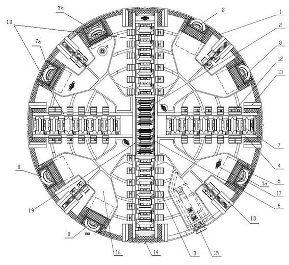
[0022] See figure 1 , a shield cutter head for complex formations, including a cutter head body 1 with a box structure, hobs are installed on the front of the cutter head body 1, and the hobs include cross-shaped knife beams 18 respectively installed through tool holders. Some single-edged standard hobs 7 on the top, some single-edged central hobs 6 installed on the inline knife beam 19 located at the center of the cross-shaped knife beam 18, 3 single-edged standard hobs 7a installed in the edge area and 4 single-edged eccentric hobs 8; wherein, five single-edged standard hobs 7 and six are cross-mounted on the cross-shaped knife beam 18 through five conjoined hob holders 3 and six conjoined hob holders 4 A single-edged standard hob 7; eight single-edged central hobs 6 arranged in concentric circles are installed on the inline knife beam 19 through eight conjoined central hob holders 2; the single-edged standard hob in the edge area The hob 7 and the single-edged eccentric ho...


PUM


Abstract

The invention discloses a shield cutter for a composite ground, which comprises a cutter head with a box body structure, wherein a hobbing cutter is arranged on the front face of the cutter head and comprises a plurality of single-blade standard hobbing cutters, a plurality of single-blade central hobbing cutters, a plurality of single-blade standard hobbing cutters and a plurality of single-blade eccentric hobbing cutters; the single-blade standard hobbing cutters are arranged on a cross cutter beam; the single-blade central hobbing cutters are arranged on a transverse I-shaped cutter beam positioned in the central area of the cross cutter beam; the single-blade standard hobbing cutters and the single-blade eccentric hobbing cutters are arranged in an edge area of the cross cutter beam; cutting knives are symmetrically arranged along the two sides of the cross cutter beam in the form of a concentric circle; edge scraping knives are arranged on the two sides of the cross cutter beam and at the middle positions of every two cutter beams of the cross cutter beam, on the edge of the front face of the cutter head; a plurality of radius retaining knives are arranged at the periphery ofthe cutter head; and an over cutter extended from the periphery is arranged in a box body of the cutter head. When the shield cutter is compared with the prior art, the boundary dimension of a cutterholder is reduced, the aperture opening ratio of the cutter is increased, the slag flowability is improved, and the wear resisting property of the whole cutter is improved.

Description

technical field [0001] The invention belongs to shield equipment, and in particular relates to a shield cutterhead used in composite formations. Background technique [0002] Compared with other construction methods, shield construction has the advantages of high degree of automation, speed, safety, efficiency, and small impact on the surface environment, so it is widely used in various underground tunnel constructions. [0003] As one of the key components of the shield machine, the cutter head is mainly used to break and strip the rock and soil of the tunnel face and support the tunnel face. The structural form and opening ratio of the cutter head, the combination form and arrangement of the cutters, the reasonable design of the wear-resistant device of the cutter head and the foam nozzle are important guarantees for the efficient tunneling of the shield machine. [0004] After the rock and soil on the face of the tunnel is broken, it enters the soil bin through the openi...

Claims


Application Information

Patent Timeline
Patent Type & Authority Applications(China)
IPC IPC(8): E21D9/08E21D9/04
Inventor 程永亮暨智勇罗孔林阳旭
Owner CHINA RAILWAY CONSTR HEAVY IND
Why Eureka
Try Eureka