Backlight module and liquid crystal display device

A technology of backlight module and light guide plate, which is applied to lighting devices, fixed lighting devices, and damage prevention measures of lighting devices, etc. The effect of avoiding shaking, low cost, and avoiding breakage

Inactive Publication Date: 2012-01-18
TCL CHINA STAR OPTOELECTRONICS TECH CO LTD
View PDF7 Cites 13 Cited by
  • Summary
  • Abstract
  • Description
  • Claims
  • Application Information

AI Technical Summary

Problems solved by technology

However, if the module is subjected to a large impact during transportation, it may cause the LGP to hit the metal rivet post violently. Since the acrylic plate (PMMA) made of LGP has poor impact resistance, under a large external impact, local Cracks are prone to appear, which will affect the display quality of the screen

Method used


Image

  • Backlight module and liquid crystal display device
  • Backlight module and liquid crystal display device
  • Backlight module and liquid crystal display device

Examples


Embodiment 1

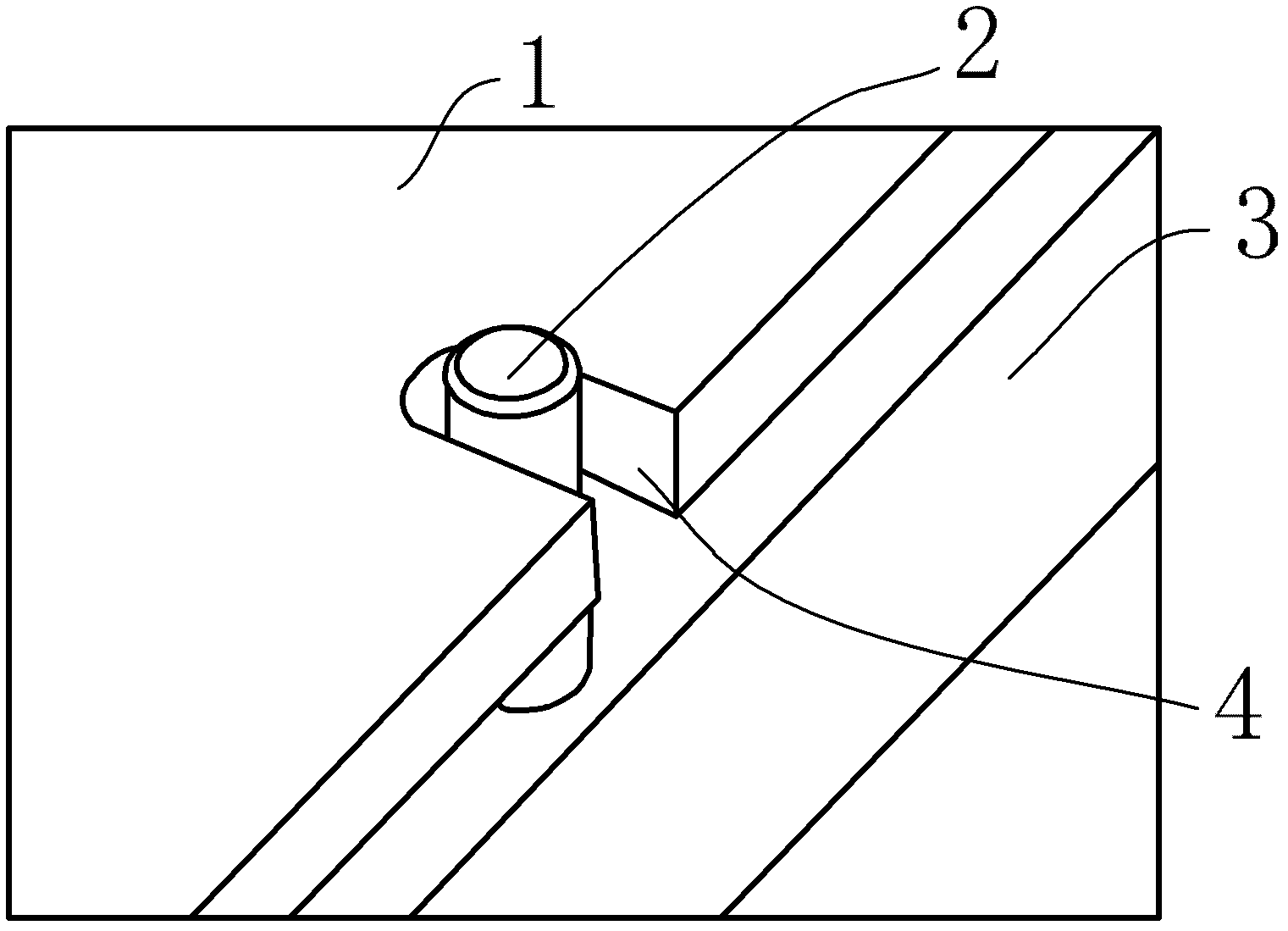
[0025] Such as figure 2 As shown, the rivet column 2 is covered with a buffer sleeve, which is made of silica gel, rubber or other foaming materials, so the buffer sleeve can be a rubber sleeve, and the rubber sleeve is provided with an inwardly extending flange at the opening Correspondingly, grooves are provided on the cylinder of the rivet column 2, and when the rubber sleeve is inserted into the cylinder, the flange can be embedded in the groove to realize the fastening of the rubber sleeve. In order to ensure the cushioning effect of the rubber sleeve, the thickness of the rubber sleeve should not be less than 1.2mm.

[0026] The method of adopting the rubber sleeve is simple in process, as long as it is installed on the existing rivet column 2, it is convenient for production and use.

[0027] The groove also surrounds the entire cylindrical surface of the rivet post, and correspondingly, the flange is also an annular flange. The ring-shaped flange and the groove coop...

Embodiment 2

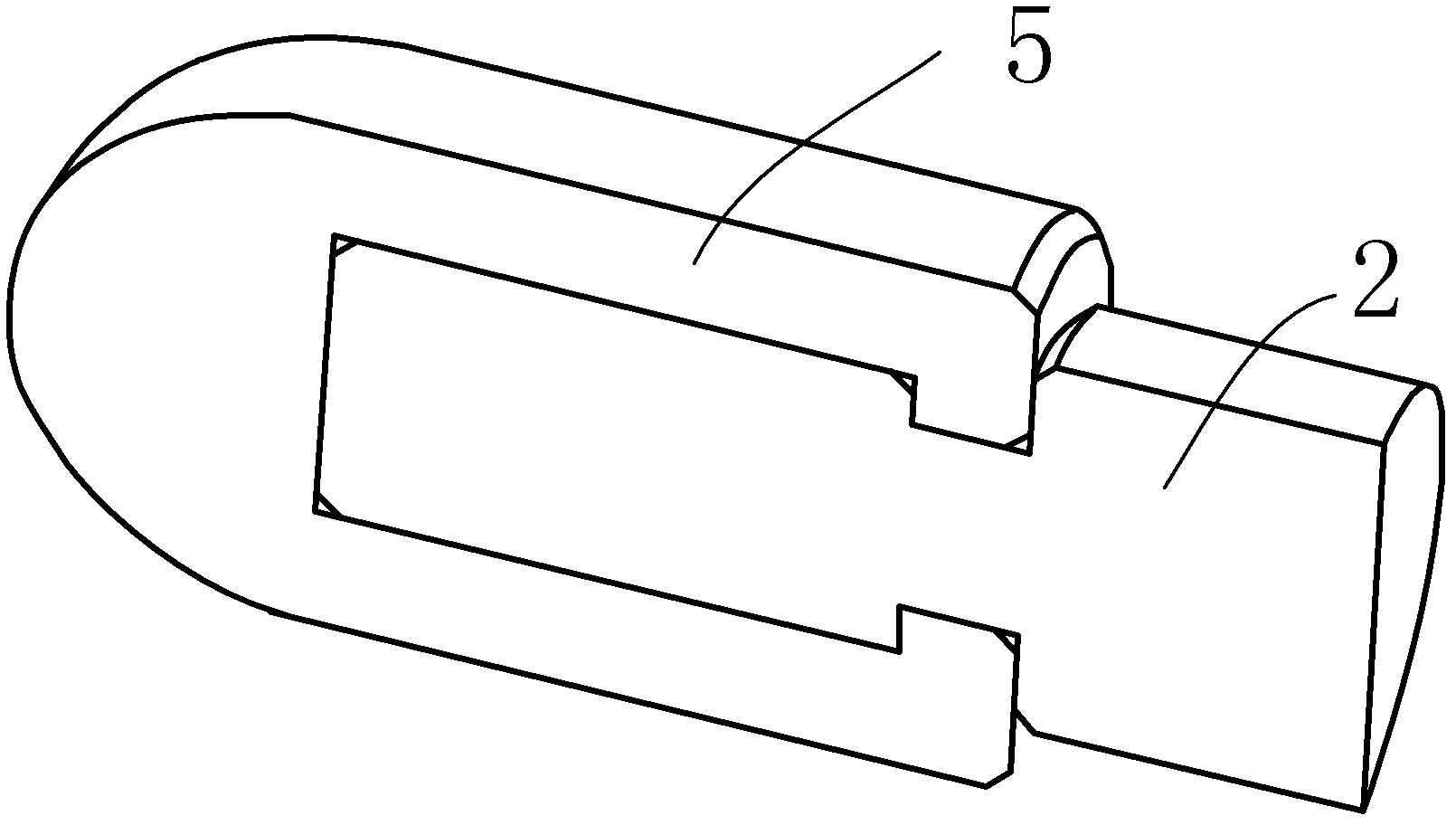
[0029] Such as image 3 As shown, in this embodiment, a buffer pad is attached to the inner surface of the notch 4 with double-sided tape, and the buffer pad can be made of silica gel, rubber or foam materials.

Embodiment 3

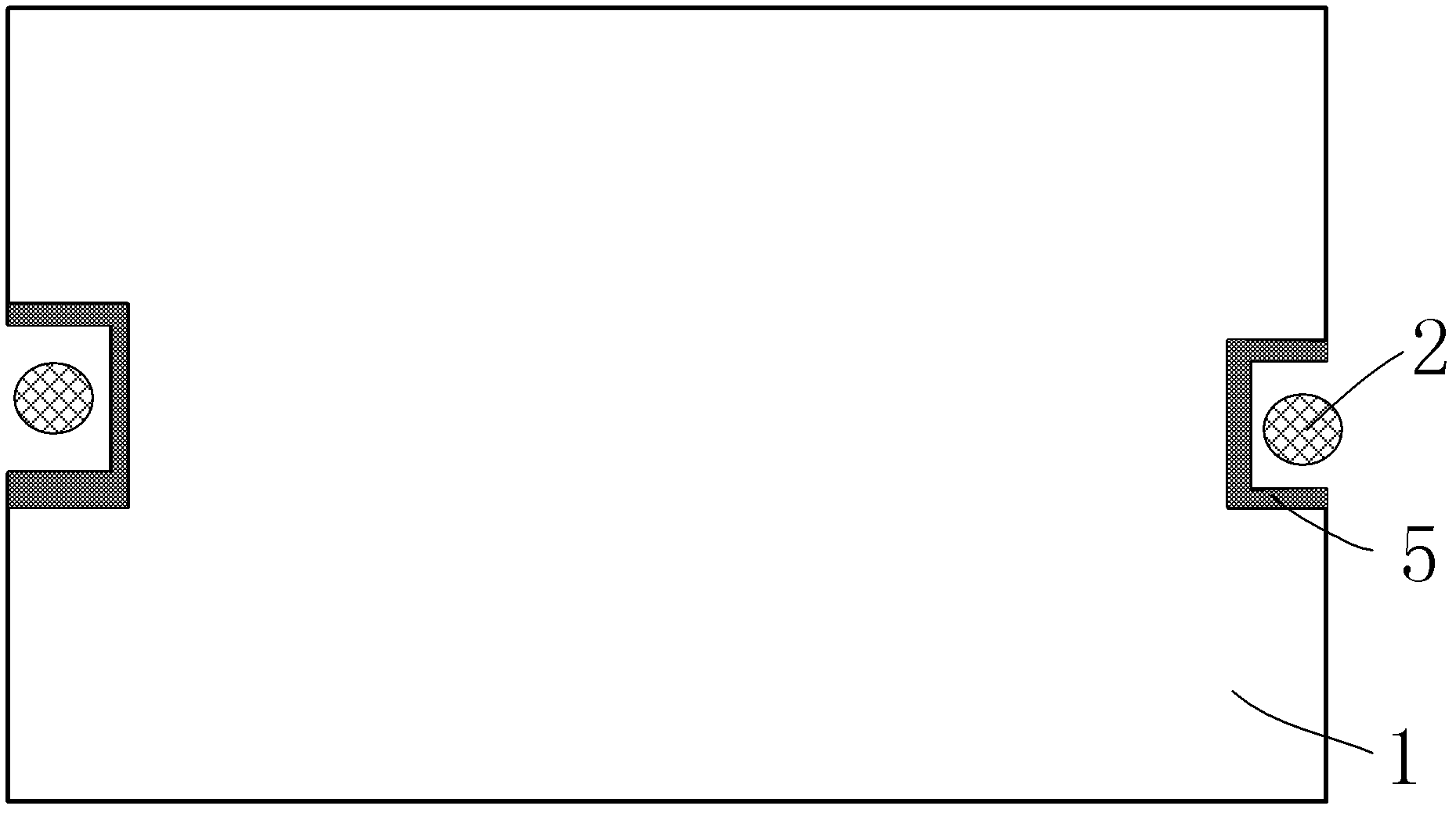
[0031] Such as Figure 4 As shown, in this embodiment, a glue dispenser is used to inject transparent elastic colloid into the gap between the notch 4 and the rivet post 2 , so that the buffer member 5 fills up all the gaps and has stronger impact resistance.

[0032] In the present invention, by adding cushioning materials such as silica gel and rubber between the gap 4 of the light guide plate 1 and the rivet post 2, effective buffering can be provided when the impact force is received, and damage caused by direct collision between the light guide plate 1 and the rivet post 2 can be avoided. , the process is simple, the material is cheap, and the low cost can be realized. In addition, when the light guide plate 1 is heated and expanded, the buffer material can also prevent the extrusion damage caused by the direct extrusion of the light guide plate 1 and the rivet post 2; The increase of the distance will easily cause shaking, and the existence of the buffer member 5 can be...


PUM

PropertyMeasurementUnit
thicknessaaaaaaaaaa

Abstract

The invention discloses a backlight module and a liquid crystal display device. The backlight module comprises a light guide plate, wherein two sides of the light guide plate are provided with a plurality of gaps respectively; the backlight module is provided with riveting columns at the gaps; and buffering pieces are arranged between the riveting columns and the gaps. Buffering materials such as silica gel, rubber and the like are arranged between the gaps and the riveting columns of the light guide plate, so effective buffering is provided when the backlight module is subjected to an impact to prevent the light guide plate from directly bumping with the riveting columns and generating damages; the process is simple; the materials are cheap; and a low cost can be realized. Moreover, the buffering pieces can ensure that the light guide plate and the riveting columns can be always kept in a close contact state to prevent the light guide plate from swaying.

Description

technical field [0001] The invention relates to the field of liquid crystal display, more specifically, to a backlight module and a liquid crystal display device. Background technique [0002] With demands for energy saving and environmental protection, the market share of liquid crystal display devices using LED backlights is rapidly increasing year by year. At present, there are mainly two common lighting methods of LEDs, edge type (Edge type) and direct type (Direct type). In the edge-lit LED backlight, a light guide plate (LGP) is required, and there is a specific distance between the light guide plate (LGP) and the light emitting surface of the LED, and the light guide plate needs to be positioned. Such as figure 1 As shown, a common way is to use metal rivets for fixing. However, if the module is subjected to a large impact during transportation, it may cause the LGP to slam into the metal rivet post. Due to the poor impact resistance of the acrylic plate (PMMA) mad...

Claims


Application Information

Patent Timeline
Patent Type & Authority Applications(China)
IPC IPC(8): F21S8/00F21V15/04G02F1/13357
CPCG02B7/00F21S8/00G02B6/0088G02B6/00F21V15/04
Inventor 李全
Owner TCL CHINA STAR OPTOELECTRONICS TECH CO LTD
Why Eureka
Try Eureka