Horizontal steel wire rope tensile testing machine

A technology of tensile testing machine and steel wire rope, applied in the direction of applying stable tension/pressure to test the strength of materials, measuring devices, instruments, etc., can solve the problems of many unsafe hidden dangers, high cost, waste of electric energy, etc., and achieve energy saving in the test process , Low production cost, and the effect of reducing the amount of labor

Active Publication Date: 2013-01-23
河南省煤科院检测技术有限公司
View PDF0 Cites 0 Cited by
  • Summary
  • Abstract
  • Description
  • Claims
  • Application Information

AI Technical Summary

Problems solved by technology

From the perspective of energy saving, safety, and environmental protection, the traditional casting method breaks the mine wire rope, and the molten metal wastes a lot of electric energy, causing many unsafe hidden dangers during casting; molten metals such as lead and zinc are harmful to the human body and are not environmentally friendly. It is not high. Before casting, the two ends of the tested steel wire rope are split, broken up, and bent. It takes a lot of time. The breaking stretch is not only expensive. Larger, it is difficult to guarantee the accuracy requirements

Method used


Image

  • Horizontal steel wire rope tensile testing machine
  • Horizontal steel wire rope tensile testing machine
  • Horizontal steel wire rope tensile testing machine

Examples


Embodiment 1

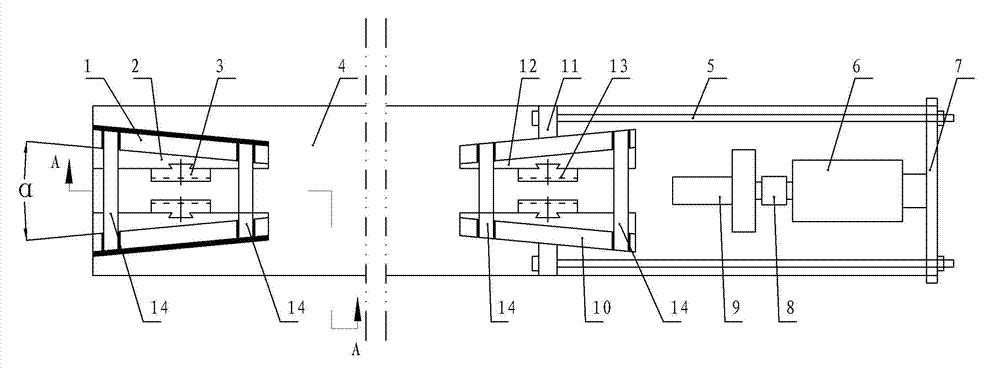
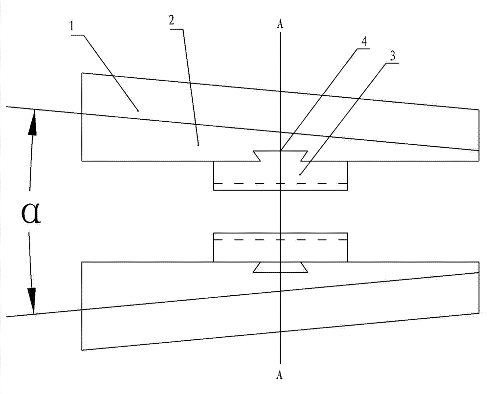
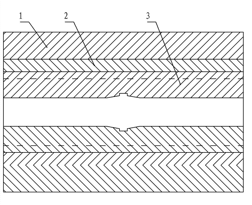
[0033] Embodiment one: figure 1 - Fig. 7, a kind of wire rope stretching fixture in the figure, contains the frame body of symmetrical arrangement, wedge-shaped slide plate, friction block, described frame body comprises two vertical plates arranged at an angle α on the inner surface, described wedge-shaped slide plate The inclination angle matches the above fixture α; the inner surface of the wedge-shaped slide plate and the friction block are connected through a vertical dovetail groove structure; the included angle is 13°≤α≤17°; the width L of the friction block is at Between 190mm and 220mm. A reinforcing connecting plate can also be added between the above two vertical plates, so as to ensure that the positional relationship between the two vertical plates remains unchanged after loading and prevent deformation. The middle part of the friction block is provided with a horizontal V-shaped clamping groove, and the surface of the V-shaped clamping groove is provided with fr...

Embodiment 2

[0036] Embodiment two: figure 1 - Fig. 7, a kind of wire rope stretching fixture in the figure, contains the frame body of symmetrical arrangement, wedge-shaped slide plate, friction block, described frame body comprises two vertical plates arranged at an angle α on the inner surface, described wedge-shaped slide plate The inclination angle matches the above fixture α; the inner surface of the wedge-shaped slide plate and the friction block are connected through a vertical dovetail groove structure; the included angle is 16°≤α≤20°; the width L of the friction block is at Between 200mm and 230mm. A reinforcing connecting plate can also be added between the above two vertical plates, so as to ensure that the positional relationship between the two vertical plates remains unchanged after loading and prevent deformation.

[0037] The middle part of the friction block is provided with a horizontal V-shaped clamping groove, and the surface of the V-shaped clamping groove is provide...

Embodiment 3

[0040] Embodiment three: figure 1 - Fig. 7, a kind of wire rope stretching fixture in the figure, contains the frame body of symmetrical arrangement, wedge-shaped slide plate, friction block, described frame body comprises two vertical plates arranged at an angle α on the inner surface, described wedge-shaped slide plate The inclination angle matches the above fixture α; the inner surface of the wedge-shaped slide plate and the friction block are connected through a vertical dovetail groove structure; the included angle is 19°≤α≤23°; the width L of the friction block is at Between 210mm and 340mm. A reinforcing connecting plate can also be added between the above two vertical plates, so as to ensure that the positional relationship between the two vertical plates remains unchanged after loading and prevent deformation.

[0041] The middle part of the friction block is provided with a horizontal V-shaped clamping groove, and the surface of the V-shaped clamping groove is provi...


PUM

PropertyMeasurementUnit
widthaaaaaaaaaa
tensile strengthaaaaaaaaaa
widthaaaaaaaaaa

Abstract

A steel wire rope tensile grip and a horizontal steel wire rope tensile tester machine thereof. The steel wire rope grip comprises a symmetrically arranged frame, a wedge-shaped slide, and a friction block (3). The frame comprises two upright plates (1) arranged such that inner surfaces thereof have therebetween an angle, a. An inclination angle of the wedge-shaped slide (2) matches a of the grip. An inner surface of the wedge-shaped slide (2) and the friction block (3) are connected therebetween by a dovetail groove structure. For angle a, 13°=a=23°. The width, L, of the friction block (3) is between 190 mm to 340 mm. The horizontal steel wire rope tensile tester machine comprises in a horizontal arrangement a pressure sensor (8), a power apparatus (6), and, comprising the grip, a fixed steel wire rope tensile grip and a mobile steel wire rope tensile grip. The power apparatus (6) and the mobile steel wire rope tensile grip are connected therebetween by a pull rod (5). The present invention is structurally simple and convenient to operate, requiring only for the machine to be fixed on the ground to allow one person to complete operations of the entire testing process, thereby reducing greatly the amount of labor of testing. Compared to existing tester machines, the machine allows for an energy-saving testing process, is safe, environmentally friendly, movable, and has both low manufacturing costs and testing costs.

Description

technical field [0001] The invention relates to the technical field of mine steel wire rope detection equipment, in particular to a horizontal steel wire rope tensile testing machine. Background technique [0002] In the field of material tensile testing, the sample must be reliably clamped to prevent slipping, so that the technical parameters such as tensile strength, yield strength, elongation, residual stress, and elastic modulus of the material can be accurately obtained. [0003] For the coal mine field, the mechanical performance requirements of the steel wire rope are relatively high, and the existing testing machine is difficult to cope with it. Due to its own design defects, the existing testing machine basically cannot do the breaking test and cannot complete the complete inspection of the mine steel wire rope. . [0004] For the mining field, as the mine goes deeper, the diameter of the hoisting wire rope used is getting thicker and thicker, the strength leve...

Claims


Application Information

Patent Timeline
Patent Type & Authority Patents(China)
IPC IPC(8): G01N3/04G01N3/08
CPCG01N3/08G01N3/04G01N2203/028
Inventor 傅泉臻
Owner 河南省煤科院检测技术有限公司
Why Eureka
Try Eureka