Multilevel voltage pumping device

A voltage pumping and multi-level technology, which is applied in the direction of output power conversion devices, electrical components, and conversion equipment without intermediate conversion to AC. problem, to achieve the effect of low cost, simplified structure and simple control

Active Publication Date: 2014-06-18
SOUTHEAST UNIV
View PDF3 Cites 0 Cited by
  • Summary
  • Abstract
  • Description
  • Claims
  • Application Information

AI Technical Summary

Problems solved by technology

Diode clamped multilevel inverters are relatively simple, but require a large number of diodes; flying capacitor multilevel inverters are more flexible than diode clamped multilevel inverters, but they also require a large number of capacitors. problem, and the multilevel inverters of these two topologies cannot realize the boost function, and the peak-to-peak value of the output AC voltage is the same as the input DC measurement voltage
The basic idea of ​​cascaded multi-level inverters is to cascade traditional single-phase inverters with independent DC power supplies, which can achieve the purpose of voltage pumping, but requires a large number of independent DC power supplies
[0004] Past studies have shown that in order to obtain new multi-level devices, innovations in the circuit structure are necessary to obtain positive results, but from the published data, new multi-level structures exist without exception. Two problems: the number of multi-level stages is determined by the number of certain or several devices in the circuit, that is, the effect of multi-level output is determined by the so-called hardware conditions, which means that if you want to get For a better multi-level effect, more devices must be added, which greatly increases the cost; second, the pumping of the output voltage is basically obtained by increasing the number of input power sources, that is, the so-called superposition of input voltages to obtain high output voltage, which also increases the cost of the device and poses challenges to the complexity of the control strategy and the safety of the system

Method used


Image

  • Multilevel voltage pumping device
  • Multilevel voltage pumping device
  • Multilevel voltage pumping device

Examples


Embodiment Construction

[0046] The present invention will be further described below in conjunction with the accompanying drawings.

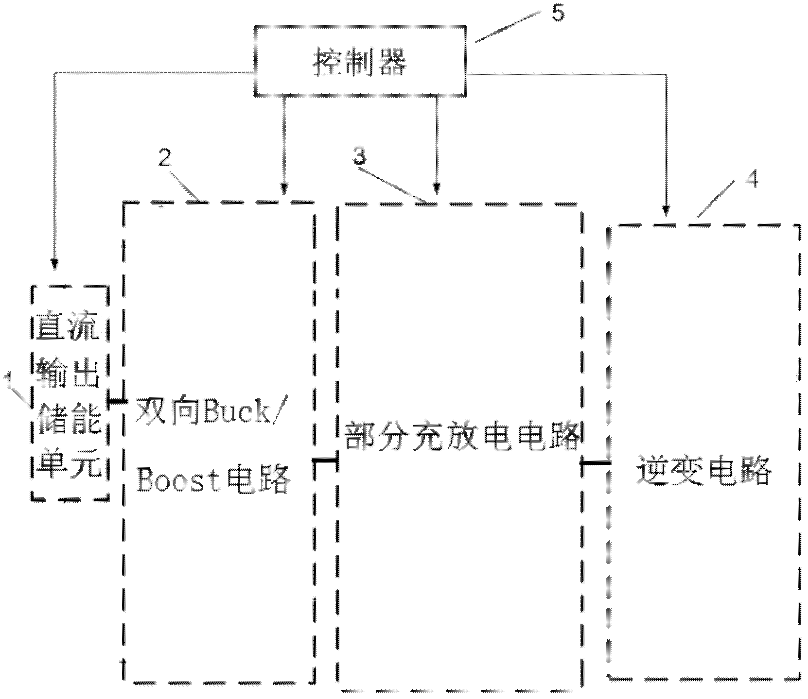
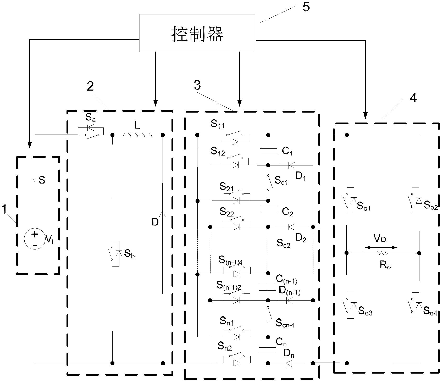
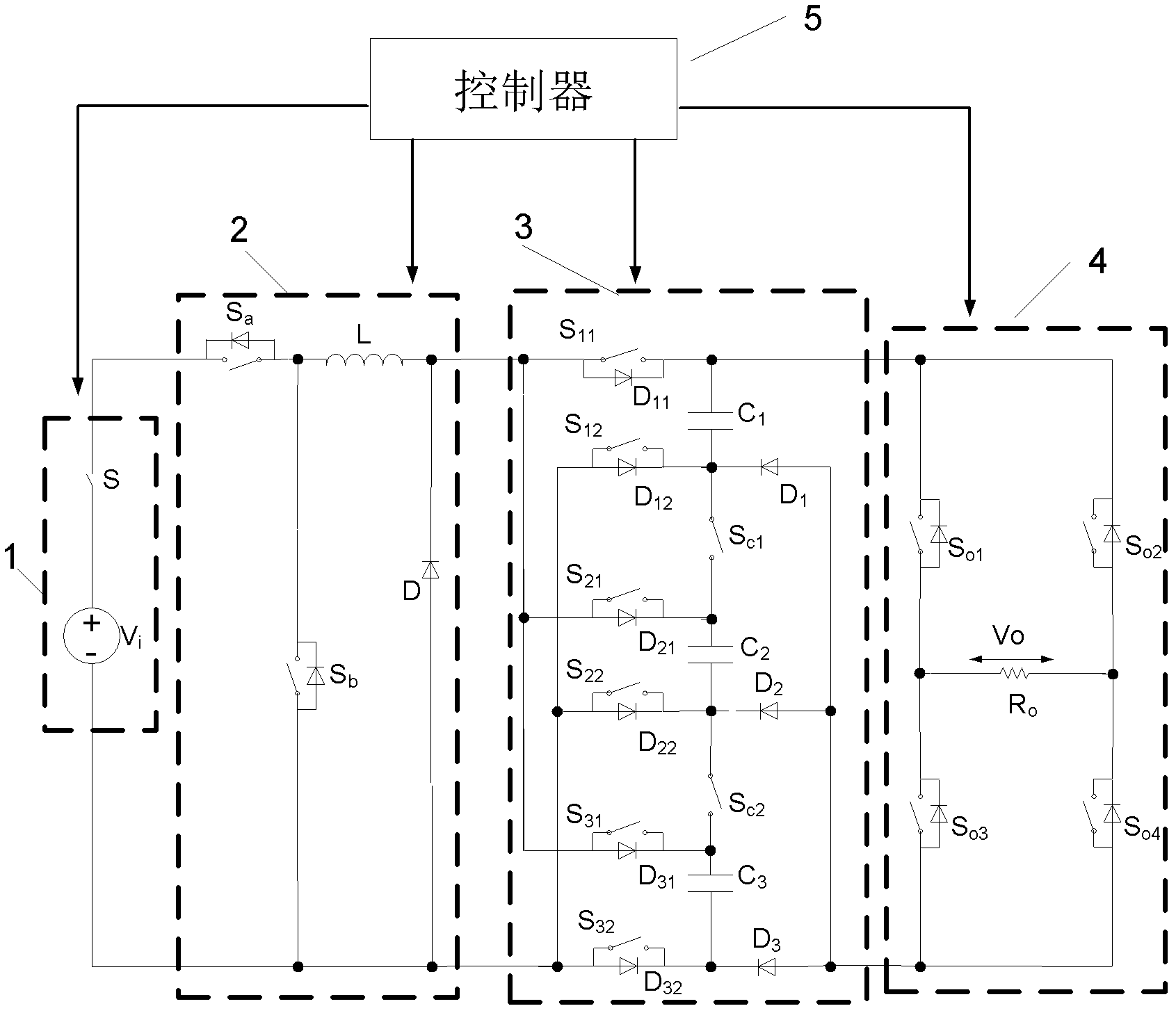
[0047] The novel voltage pumping multi-level device provided by the present invention, as attached figure 2 As shown in , the device includes a DC output energy storage unit (1), a bidirectional Buck / Boost circuit (2), followed by a charging and discharging power switching device S 11 , S 12 , S 21 , S 22 ..., S n1 , S n2 (The above power switches all need to connect reverse diodes in parallel), capacitor C 1 、C 2 ,...C n and voltage pumping power switching device S C1 , S C2 ..., S Cn-1 Part of the charging and discharging circuit (3) is composed, and then connected by the power switching device S o1 , S o2 , S o3 , S o4 The inverter circuit (4) composed of (the above power switches all need to be connected in parallel with reverse diodes); the controller (5) is mainly used to generate PWM waves to control the power switching devices in the circuit.

...


PUM


Abstract

The invention relates to a multilevel voltage pumping device. One set of multilevel main inverter circuits capable of realizing voltage pumping output is combined with the corresponding on-off control policy, and the waveform of the output voltage has good sinusoidal property. Meanwhile, the pumping of the output voltage is realized in relative to input. The hardware circuit of the device comprises a DC output energy storage unit and a bidirectional Buck / Boost circuit and is followed by a partial charging and discharging circuit and an inverter circuit, wherein the partial charging and discharging circuit comprises charging and discharging power switches S11, S12, S21, S22... ...,Sn1, Sn2, capacitors C1, C2... ...Cn and voltage pumping power switches SC1, SC2... ...,SCn; the inverter circuit comprises power switches So1, So2, So3 and So4. A controller is mainly used for generating control signals and is used for driving the power switches in the control circuit. A new topological structure is put forward by using the existing DC-DC voltage pumping and multilevel inverting ideas, and the output voltage with excellent sinusoidal property is realized.

Description

technical field [0001] The invention belongs to the field of power electronics and power supply, and relates to a novel voltage pump multi-level device and its control strategy, which is suitable for electric vehicles and other power supply occasions where electric energy is provided by a DC output energy storage unit. Background technique [0002] With the increasingly prominent energy problems and environmental pollution, people are paying more and more attention to green energy and the ecological environment. Replacing traditional internal combustion engine vehicles with electric vehicles has become one of the current research hotspots, and the power supply for electric vehicles is generally through inverters. The AC power supplied by the inverter will inevitably generate harmonics and interference, which will directly affect the operating performance of electric vehicles. It is urgent to find a power supply with low harmonic content. Compared with the traditional two-lev...

Claims


Application Information

Patent Timeline
Patent Type & Authority Patents(China)
IPC IPC(8): H02M7/42H02M3/07H02M7/48H02M1/14
Inventor 程明丁石川邹国棠王政花为
Owner SOUTHEAST UNIV
Why Eureka
Try Eureka