
Frequency change system group delay test method

A technology of frequency conversion system and test method, which is applied in transmission systems, digital transmission systems, electrical components, etc., to achieve the effects of flexible testing, elimination of time delay measurement errors, and high measurement accuracy

Active Publication Date: 2012-01-18
BEIJING INST OF SPACECRAFT SYST ENG
View PDF2 Cites 35 Cited by
  • Summary
  • Abstract
  • Description
  • Claims
  • Application Information

AI Technical Summary

Problems solved by technology

[0006] The technical problem of the present invention is: to overcome the deficiencies of the prior art, to provide a frequency conversion system group time delay test method that occupies less hardware resources, has high measurement accuracy, is simple to implement, and has strong versatility, and solves the problem of precision measurement of frequency conversion systems. delay problem

Method used


Image

  • Frequency change system group delay test method
  • Frequency change system group delay test method
  • Frequency change system group delay test method

Examples


Embodiment 1

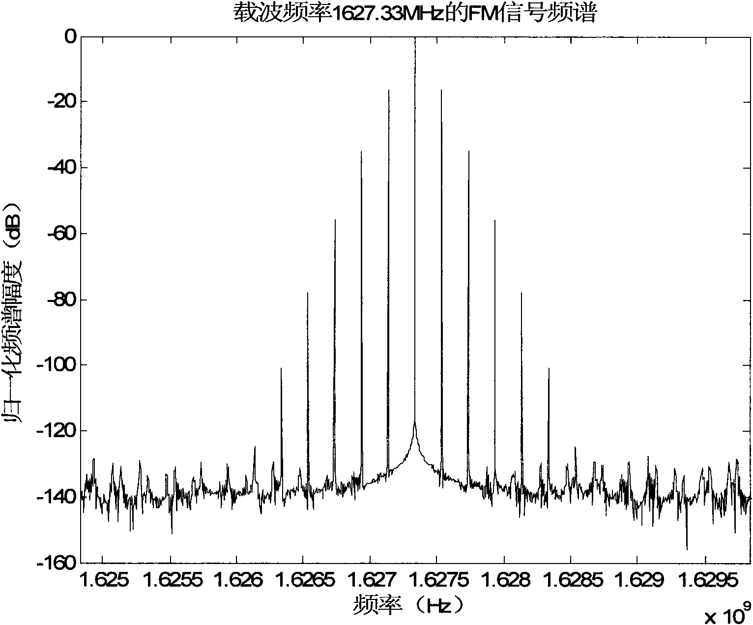
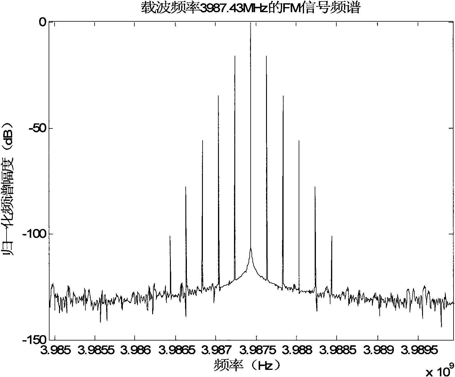
[0044] The input center frequency of the simulated frequency conversion system is 1627.33MHz, the corresponding output center frequency is 3987.43MHz, and the set group delay when the frequency conversion system works at the center frequency is 700ns.

[0045] 1. Use the frequency sweep signal source to generate a single carrier, the single carrier frequency is 1627.33MHz, use the low frequency signal source to generate a periodic low frequency signal as the baseband signal, and use the FM modulator to perform FM narrowband modulation on the single carrier generated by the frequency sweep signal source. The FM carrier modulation signal is formed, the frequency of the low frequency signal used for the first time is 200kHz, and the frequency offset constant is 10000;

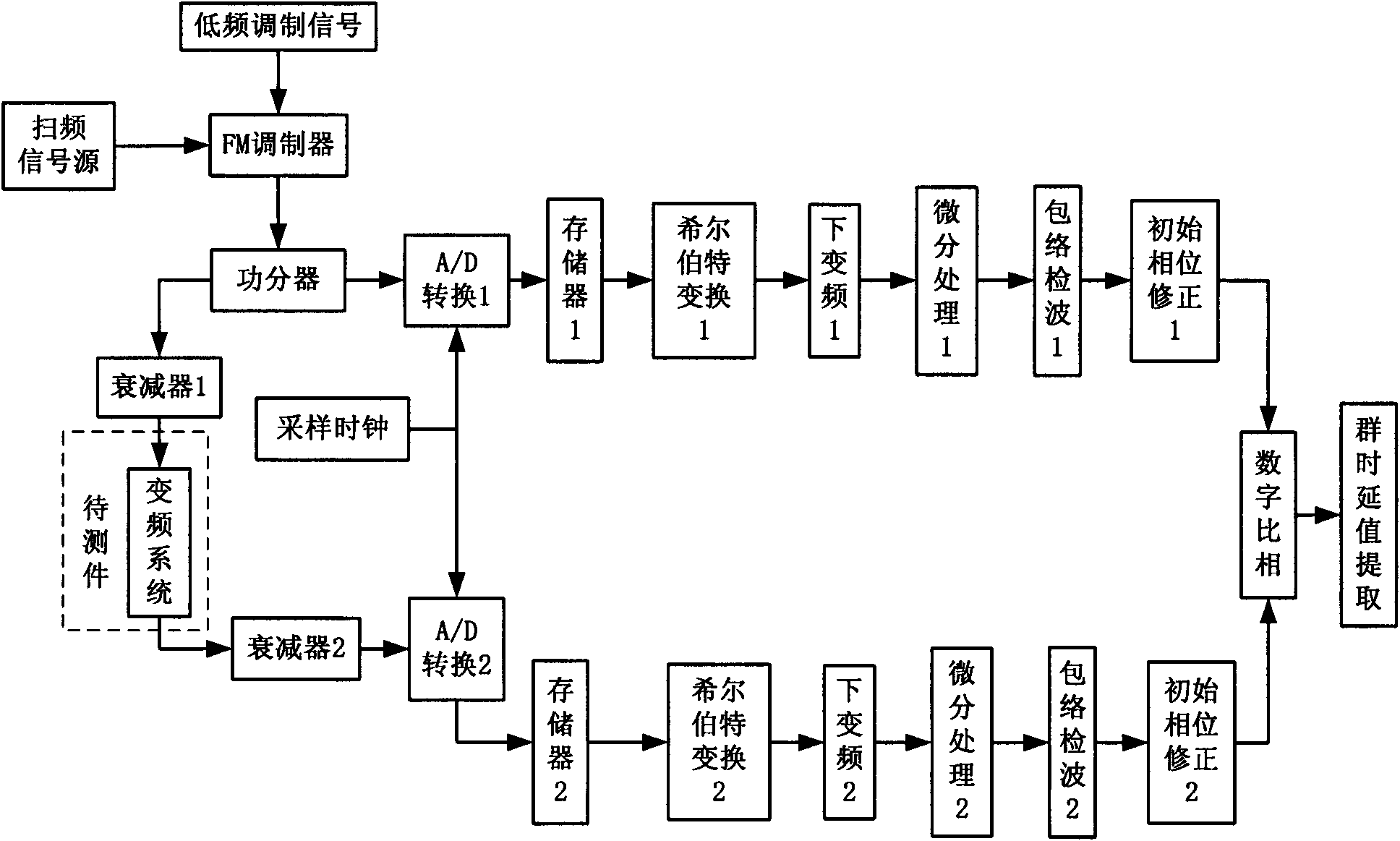
[0046] 2. Divide the FM narrowband modulation signal into two channels, one is used as the input of the first A / D converter; For the input of the D converter, the two A / D converters are controlled by the same refe...

Embodiment 2

[0055] The input center frequency of the simulated frequency conversion system is 1627.33MHz, the corresponding output center frequency is 16.5GHz, and the set group delay when the frequency conversion system works at the center frequency is 700ns.

[0056] 1. Use the frequency sweep signal source to generate a single carrier, the single carrier frequency is 1627.33MHz, use the low frequency signal source to generate a periodic low frequency signal as the baseband signal, and use the FM modulator to perform FM narrowband modulation on the single carrier generated by the frequency sweep signal source. The FM carrier modulation signal is formed, the frequency of the low frequency signal used for the first time is 200kHz, and the frequency offset constant is 10000;

[0057] 2. Divide the FM narrowband modulation signal into two channels, one is used as the input of the first A / D converter; For the input of the D converter, the two A / D converters are controlled by the same referen...


PUM


Abstract

The invention relates to a frequency change system group delay test method which comprises the following steps of: generating an FM (Frequency Modulation) carrier signal of which the carrier frequency is the center frequency of a working frequency band of a frequency change system by a signal source; then dividing the signal into two paths, wherein one path of signal is input to the frequency change system by an attenuator and used as the input of a first A / D (Analog-to-Digital) converter by the attenuator after being output by the frequency change system, the other path of signal is used as the input of a second A / D converter, and the two A / D converters synchronously sample data by using the same reference clock; then respectively carrying out Hilbert transformation, digital down conversion and non-coherent demodulation on two paths of A / D sampled data; and carrying out digital phase comparison on the two paths of demodulated base band signals to obtain a group delay value of the frequency change system. A group delay test result of all frequency points of the frequency change system in the frequency band can be obtained by changing the carrier frequency of the FM carrier signal in the working bandwidth of the frequency change system and repeating the processing; and the measuring precision depends on system heat noise, the correcting precision of a test cable and A / D sampling resolution.

Description

technical field [0001] The invention relates to a frequency conversion system group time delay testing method, which is used for precise measurement of the frequency conversion system group time delay. Background technique [0002] Group delay is an important parameter to describe the phase and frequency characteristics of the frequency conversion system, and an important index to measure the phase linearity of the continuous signal passing through the frequency conversion system. The group delay not only determines the size of the signal transmission delay generated by the system or network, but also is closely related to the signal transmission distortion, which has a great impact on the signal transmission quality. [0003] At present, the main test methods for the group delay of the frequency conversion system are: [0004] (1) Method based on vector network analyzer. The commonly used solution is the vector mixer calibration technology, which uses the calibration mixe...

Claims


Application Information

Patent Timeline
Patent Type & Authority Applications(China)
IPC IPC(8): H04L12/26
Inventor 崔小准李鹏聂欣米红李懿刘庆军刘家兴钟兆丰
Owner BEIJING INST OF SPACECRAFT SYST ENG
Learn More