Positioning method in novel silk screen printing CCD (charge coupled device) image identification

A technology of image recognition and positioning method, which is applied to screen printing machines, printing machines, printing machines, etc., can solve problems affecting printing accuracy and achieve high-precision alignment accuracy

Inactive Publication Date: 2012-01-25
PANDA ELECTRONICS GROUP +1
View PDF7 Cites 33 Cited by
  • Summary
  • Abstract
  • Description
  • Claims
  • Application Information

AI Technical Summary

Problems solved by technology

The general CCD image recognition and positioning method cannot realize the precise recognition and p

Method used


Image

  • Positioning method in novel silk screen printing CCD (charge coupled device) image identification
  • Positioning method in novel silk screen printing CCD (charge coupled device) image identification
  • Positioning method in novel silk screen printing CCD (charge coupled device) image identification

Examples


Embodiment Construction

[0015] The present invention will be further described below in conjunction with the accompanying drawings and embodiments.

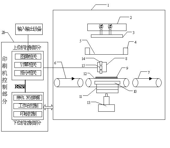
[0016] Such as figure 1 Shown is the structural schematic diagram of the whole screen printing device. exist figure 1 Shown in 1 is the mechanical structure, 20 is the control part, and the control is divided into upper computer (PC) control and lower computer (PLC) control. The upper computer provides the human-computer interaction interface and image processing and the calculation of the position deviation of the MARK point; the lower computer accepts the instructions of the upper computer to drive the relevant movements of the mechanical parts. The adopted structure is that the transmission part has three parts: the incoming part 6, the workbench transmission part 12, and the outgoing part 7. The workbench part 10 has main functions of positioning the PCB board 9 and the workbench lifting part 13 . Image acquisition device 8, its main components ...


PUM


Abstract

The invention discloses a positioning method in novel silk screen printing CCD (charge coupled device) image identification, comprising the following steps of: (a) conveying PCBs (printed circuit boards) to an operating platform part to be initially positioned and clamped by virtue of an introducing part and an operating platform conveying part; (b) obtaining a CCD positioning identification template by adopting a manually programming method; (c) calculating angular deviation and distance deviation by virtue of the PCBs and MARK points on a silk screen, controlling the operating platform to correspondingly adjust position and angle; and (d) moving an image acquisition device to the position above the PCBs and the MARK points, respectively shooting the PCBs and the MARK points of the silk screen by virtue of a CCD camera, matching the obtained image with the CCD positioning identification template, and carrying out automatic printing after a matching requirement is achieved. The invention provides a whole set of system, the system can automatically detect offset between the center of an object window required to be retrieved by a user and the center of any pattern, the offset is namely correction, the correction is added during counterpoint calculation, and counterpoint actuating quantity is calculated and a counterpoint action is executed. For various patterns used for counterpoint of a base plate, the various patterns can be simply counterpointed without high correction proficiency requirement, and printing counterpoint accuracy can be improved.

Description

technical field [0001] The invention relates to the technical field of CCD image recognition, in particular to a novel positioning method for screen printing CCD image recognition. Background technique [0002] In the SMT industry, the screen printing device is an important component device. The general screen printing device is divided into: incoming substrate transmission part, workbench part with lifting mechanism and substrate clamping and positioning, outgoing substrate conveying part, screen part corresponding to the substrate, scraper, with scraper lifting mechanism and The knife head of the horizontal movement mechanism, the control device for controlling each mechanism, and the CCD identification device. When the substrate arrives at the workbench through the incoming transmission part, the workbench temporarily clamps and fixes the substrate once, and then uses the CCD to identify the substrate and the two sides of the screen corresponding to the pattern of the su...

Claims


Application Information

Patent Timeline
IPC IPC(8): B41F15/34
Inventor 邹垂国潘红斌路小军杨定香何杏兴
Owner PANDA ELECTRONICS GROUP
Why Eureka
Try Eureka