Symmetric rotation piezoelectric generation device

A power generation device and rotary pressure technology, applied in the field of micro energy, can solve the problems of narrow response bandwidth, reduced service life, loss of mechanical energy, etc., and achieve the effect of increasing response bandwidth, avoiding energy loss, and avoiding life reduction

Inactive Publication Date: 2012-01-25
DALIAN UNIV OF TECH
View PDF5 Cites 42 Cited by
  • Summary
  • Abstract
  • Description
  • Claims
  • Application Information

AI Technical Summary

Problems solved by technology

[0003] Shashank Priya invented a mechanical contact collision type rotating piezoelectric power generation device (invention patent number: US 2010/0052324A1). Disadvantages of service life
J.Rastegar and R.Murry proposed the concept of two-stage rotary piezoelectric generators (J.Rastegar and R.Murray. Novel two-stage piezoelectric-bas...

Method used


Image

  • Symmetric rotation piezoelectric generation device
  • Symmetric rotation piezoelectric generation device
  • Symmetric rotation piezoelectric generation device

Examples


Embodiment Construction

[0011] The specific implementation manner of the present invention will be described in detail in conjunction with the accompanying drawings and technical solutions. The basic principle of the invention is based on the principle of bistable potential energy, and a symmetrical rotary piezoelectric generator is invented, which improves the response bandwidth of the rotary piezoelectric generator and increases the output power.

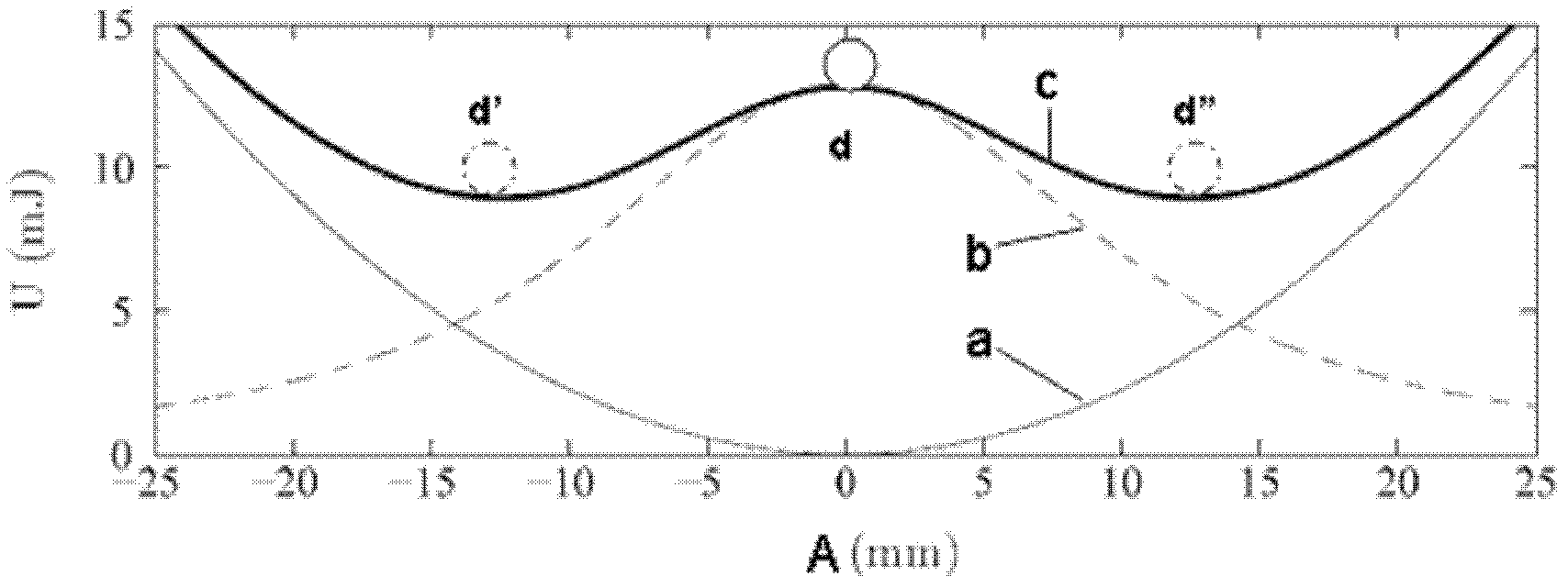
[0012] attached figure 1 It shows the schematic diagram of the bistable potential energy of the piezoelectric bicrystal beam. In the figure, the thin solid line represents the recovery energy a of the piezoelectric bicrystal beam, the dotted line represents the magnetic potential energy b, and the thick solid line represents the total potential energy c. It can be seen from the figure that when the total potential energy c of the piezoelectric bicrystalline beam is in the bistable energy state, there are two lowest positions of potential energy, namely, ...


PUM


Abstract

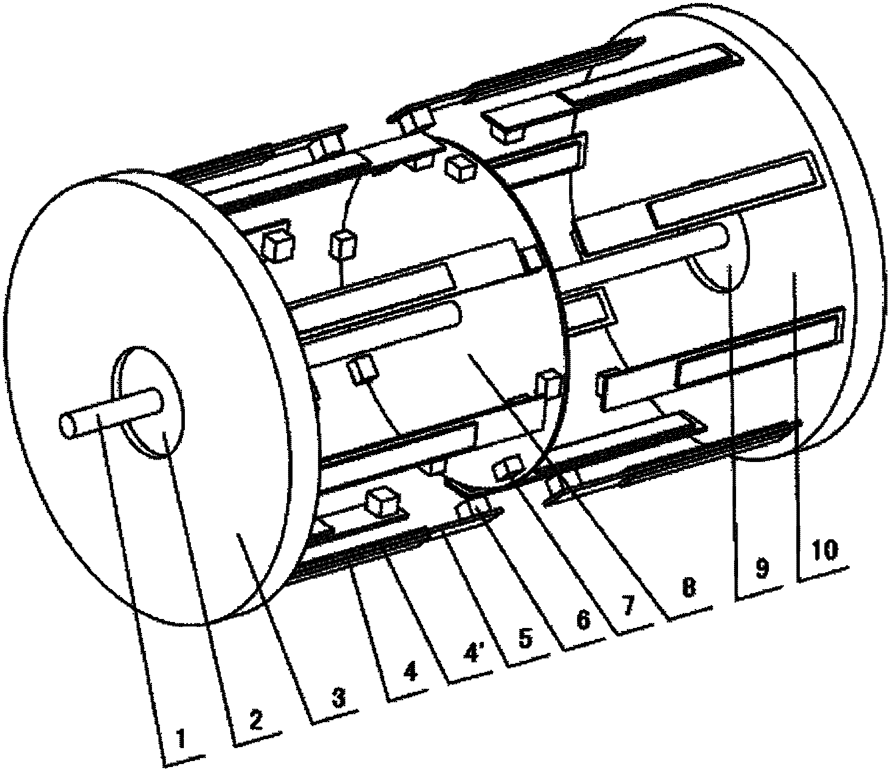
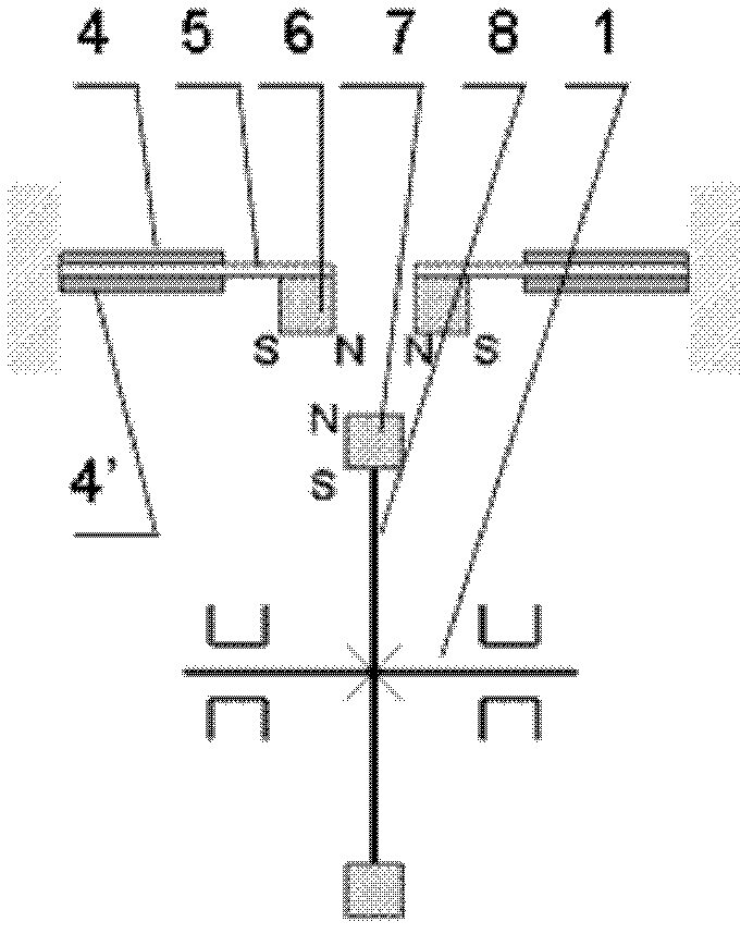
The invention discloses a symmetric rotation piezoelectric generation device which belongs to the technical field of micro energy and is particularly suitable for collecting varying rotation mechanical energy in a low-frequency vibration environment. The generation device consists of a rotation shaft, left and right bases, left and right bearings, left and right piezoelectric bi-crystal beam arrays, an excitation wheel permanent magnet array and an excitation wheel. The excitation wheel is in rigid connection with the rotation shaft; and the rotation shaft is supported in the center holes of the left and the right bases by the left and the right bearings respectively. In the generation device, the left and the right piezoelectric bi-crystal beam arrays are completely symmetric in structure. The excitation wheel permanent magnet array consisting of multiple excitation wheel permanent magnets is uniformly arranged at the periphery of the left side of the excitation wheel; each piezoelectric bi-crystal beam is composed of a permanent magnet block, a copper beam and a piezoelectric ceramic chip; and the piezoelectric bi-crystal beam array consisting of the left and the right piezoelectric bi-crystal beams is uniformly mounted on the left and the right bases. The device transfers the acting force by use of non-contact permanent magnetic force, thereby avoiding the energy loss and service life reduction caused by mechanical impact, and increasing the response bandwidth of a common rotation piezoelectric generation device.

Description

technical field [0001] The invention is a symmetrical rotating piezoelectric power generation device belonging to the field of micro-energy technology, which is particularly suitable for collecting rotational mechanical energy changing in a low-frequency vibration environment. Background technique [0002] Vibration in the environment is characterized by low frequency and random changes. At present, the main methods of using piezoelectric technology to obtain environmental vibration energy include: resonance adjustment, combined, frequency-increasing, and nonlinear vibration. Among them, the frequency-increasing piezoelectric power generation has a simple structure and high efficiency, and has attracted increasing attention. The main features of frequency-increased piezoelectric power generation: use mechanical collision or non-contact impact to increase the response frequency of the piezoelectric cantilever, and increase the output power of the piezoelectric cantilever. ...

Claims


Application Information

Patent Timeline
IPC IPC(8): H02N2/18
Inventor 褚金奎韩冰峰熊叶胜姚斐
Owner DALIAN UNIV OF TECH
Why Eureka
Try Eureka