Magnetic suspension bearing control system and magnetic suspension bearing

A magnetic suspension bearing and control system technology, applied in the field of magnetic suspension, to increase the system response bandwidth, solve the contradiction between signal-to-noise ratio and dynamic response performance, and improve the response speed

Active Publication Date: 2021-01-19
TIANJIN EMAGING TECH
View PDF7 Cites 1 Cited by
  • Summary
  • Abstract
  • Description
  • Claims
  • Application Information

AI Technical Summary

Problems solved by technology

[0004] The purpose of the present invention is to provide a magnetic suspension bearing control system and a magnetic suspension bearing, so as to alleviate the technical problem existing in the prior art that both the reduction of electromagnetic interference and the improvement of the dynamic performance of the magnetic suspension bearing cannot be taken into account at the same time

Method used


Image

  • Magnetic suspension bearing control system and magnetic suspension bearing
  • Magnetic suspension bearing control system and magnetic suspension bearing
  • Magnetic suspension bearing control system and magnetic suspension bearing

Examples


Embodiment 1

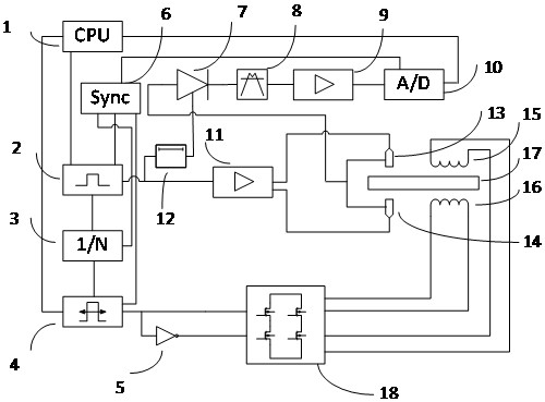
[0029] figure 1 A schematic structural diagram of a magnetic suspension bearing control system provided in an embodiment of the present invention, including: a processor 1, a synchronous signal generation module 2, and a displacement signal conversion circuit (by figure 1 In the first amplifier circuit 11, the first sensor probe 13 and the second sensor probe 14), the post-processing circuit (composed of the rectifier circuit 7, the filter circuit 8 and the second amplifier circuit 9), the A / D conversion module 10, the pulse Wide modulation module 4 , frequency division circuit 3 , synchronization module 6 and power amplifier 18 . The above-mentioned processor 1 is an abbreviation of digital signal processor 1 , and the post-processing circuit is an abbreviation of sensor signal post-processing circuit, and the power amplifier 18 can also be called a power device.

[0030] The connection relationship between the above-mentioned components is as follows: processor 1, synchrono...

Embodiment 2

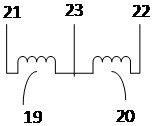
[0058] Figure 5 It is a schematic structural diagram of a magnetic suspension bearing provided by an embodiment of the present invention. The magnetic suspension bearing provided in this embodiment includes: the magnetic suspension bearing control system 100 described in Embodiment 1, the first iron core ( Figure 5 not shown), the first magnetic suspension bearing actuator coil 15 wound on the first iron core, the second iron core, the second magnetic suspension bearing actuator coil 16 wound on the second iron core, and the electromagnetic suspension Rotor 17; the first magnetic suspension bearing actuator coil 15 and the second magnetic suspension bearing actuator coil 16 are arranged in parallel on the upper and lower sides of the electromagnetic force suspension rotor 17, and the first magnetic suspension bearing actuator coil 15 and the second magnetic suspension bearing act as The actuator coils 16 are all connected to the magnetic suspension bearing control system 10...


PUM


Abstract

The invention provides a magnetic suspension bearing control system and a magnetic suspension bearing, and relates to the technical field of magnetic suspension. The magnetic suspension bearing control system comprises a processor, a synchronization signal generation module, a displacement signal conversion circuit, a post-processing circuit, an A / D conversion module, a pulse width modulation module, a frequency division circuit, a synchronization module and a power amplifier. Under the common effect of all the elements, The A / D conversion module and the power amplifier are synchronized through the synchronization signal sent by the synchronization module, the impact current and impact voltage interference caused by a device switch in the power amplifier are effectively avoided, the response bandwidth of the system can be increased, the response speed is increased, and the contradiction between the signal-to-noise ratio and the dynamic response performance is effectively solved.

Description

technical field [0001] The invention relates to the technical field of magnetic suspension, in particular to a magnetic suspension bearing control system and a magnetic suspension bearing. Background technique [0002] In order to make the structure of the existing magnetic bearing compact, and to make the position of the displacement signal and the force of the magnetic bearing as close as possible, the displacement sensor is usually installed at a position close to the electromagnet coil. It is easy to interfere with the sensor signal. In order to reduce electromagnetic interference and ensure a high signal-to-noise ratio, it is usually necessary to low-pass filter the sensor signal. In order to obtain smaller noise, the low-pass filter needs to use a higher order and a lower cut-off frequency. This method introduces The large delay reduces the dynamic performance of the magnetic suspension bearing; on the contrary, in order to obtain better dynamic performance, a low-pas...

Claims


Application Information

Patent Timeline
Patent Type & Authority Applications(China)
IPC IPC(8): F16C32/04
CPCF16C32/0455F16C32/0446F16C32/0457F16C32/0474F16C2300/12
Inventor 沙宏磊洪申平俞天野衣存宇刘万虎李凯韩景超
Owner TIANJIN EMAGING TECH
Why Eureka
Try Eureka