Circuit arrangement and method for operating at least one discharge lamp

A technology for circuit devices and discharge lamps, which is applied in the field of circuit devices and can solve problems such as discharge lamps not being ruled out of running status

Inactive Publication Date: 2016-05-25
OSRAM GMBH
View PDF2 Cites 0 Cited by
  • Summary
  • Abstract
  • Description
  • Claims
  • Application Information

AI Technical Summary

Problems solved by technology

[0004] Therefore, an operating state in which inherent flicker occurs has not been ruled out hitherto for the discharge lamps in question.

Method used


Image

  • Circuit arrangement and method for operating at least one discharge lamp
  • Circuit arrangement and method for operating at least one discharge lamp
  • Circuit arrangement and method for operating at least one discharge lamp

Examples


Embodiment Construction

[0033] For the different embodiments of the circuit arrangement according to the invention shown in the figures, the same reference symbols are used for identical and identically acting components. These reference numerals are therefore identified only once, so that the embodiment can mainly be limited to the differences from the previously described embodiment.

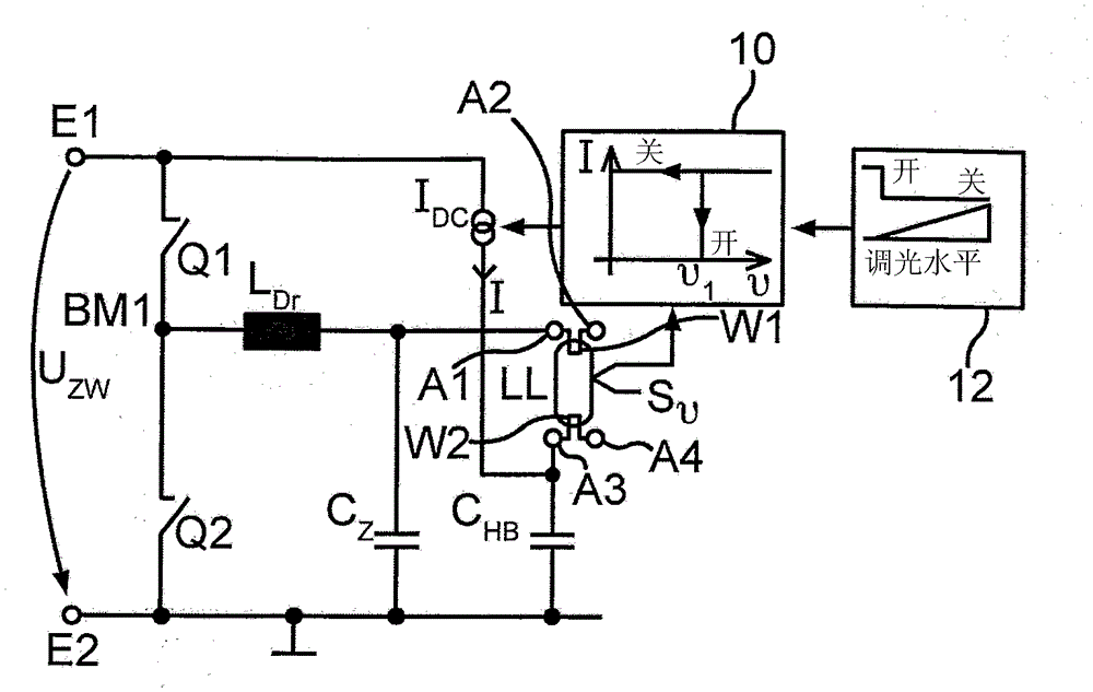
[0034] figure 1 A first exemplary embodiment of a circuit arrangement according to the invention is shown in a schematic diagram. A DC voltage source is arranged between the first input connection E1 and the second input connection E2 of the circuit arrangement, which may in particular be a so-called intermediate circuit voltage U drawn from the AC network. Zw . A series circuit of a first electronic switch Q1 and a second electronic switch Q2 is coupled as part of an inverter between the input connections E1 , E2 , a first bridge midpoint BM1 being formed between the switches Q1 , Q2 .

[0035] Lamp choke L Dr C...


PUM


Abstract

The configuration has a bridge circuit provided with electronic switches (Q1, Q2). The electronic switches form a bridge midpoint (BM1) of the bridge circuit, where the electronic switches are serially coupled between input terminals (E1, E2). Output terminals (A1, A2) are provided for coupling a discharge lamp (LL) with a coil (W1). A sensor device detects an operational parameter of the discharge lamp. A control device (10) is designed to vary amplitude (I) of a direct current power source (IDC) delivered by direct current based on the operational parameter of the lamp. The sensor device is designed as a temperature sensor. An independent claim is also included for a method for operating a discharge lamp at a circuit configuration.

Description

technical field [0001] The invention relates to a circuit arrangement for operating at least one discharge lamp, which circuit arrangement has an input with a first input connection and a second input connection for coupling to a DC voltage source, a bridge circuit with At least one first electronic switch and a second electronic switch and at least one coupling capacitor, wherein the first electronic switch and the second electronic switch are connected in series between the first input terminal and the midpoint of the first bridge with which the bridge circuit is designed Between the second input connection; the first output connection and the second output connection for coupling with the upper (hochliegenden) filament of the discharge lamp; the third output connection for coupling with the lower (tiefliegenden) filament of the discharge lamp and a fourth output connection; a lamp choke coil connected in series between the midpoint of the first bridge and any one of the out...

Claims


Application Information

Patent Timeline
Patent Type & Authority Patents(China)
IPC IPC(8): H05B41/295H05B41/39
CPCH05B41/2988H05B41/3921Y10S315/04
Inventor 彼得·克鲁莫尔
Owner OSRAM GMBH
Why Eureka
Try Eureka