Ground-heating thermal insulation layer

An insulation layer and floor heating technology, applied in insulation and building components, etc., can solve the problems of heat loss of insulation boards, reduce insulation efficiency, and complicated fixing methods, so as to reduce material costs, improve insulation efficiency, improve mechanical strength and service life Effect

Inactive Publication Date: 2012-02-01
QING DAO HAIJING PACKING MATERIALS
View PDF5 Cites 7 Cited by
  • Summary
  • Abstract
  • Description
  • Claims
  • Application Information

AI Technical Summary

Problems solved by technology

The insulation layer is generally made of EPS and other heat insulation materials. At present, the structure of the floor heating insulation layer commonly used in the market is relatively simple. The floor heating pipes are fixed on the insulation layer with structural parts such as pipe clamps. The fixing method is complicated and the cost is correspondingly increased. , and the floor heating insulation layer is laid on the ground in the way of splicing two insulation panels, so that there will be heat loss between the insulation panels, which reduces the insulation efficiency

Method used


Image

  • Ground-heating thermal insulation layer
  • Ground-heating thermal insulation layer
  • Ground-heating thermal insulation layer

Examples


Embodiment 1

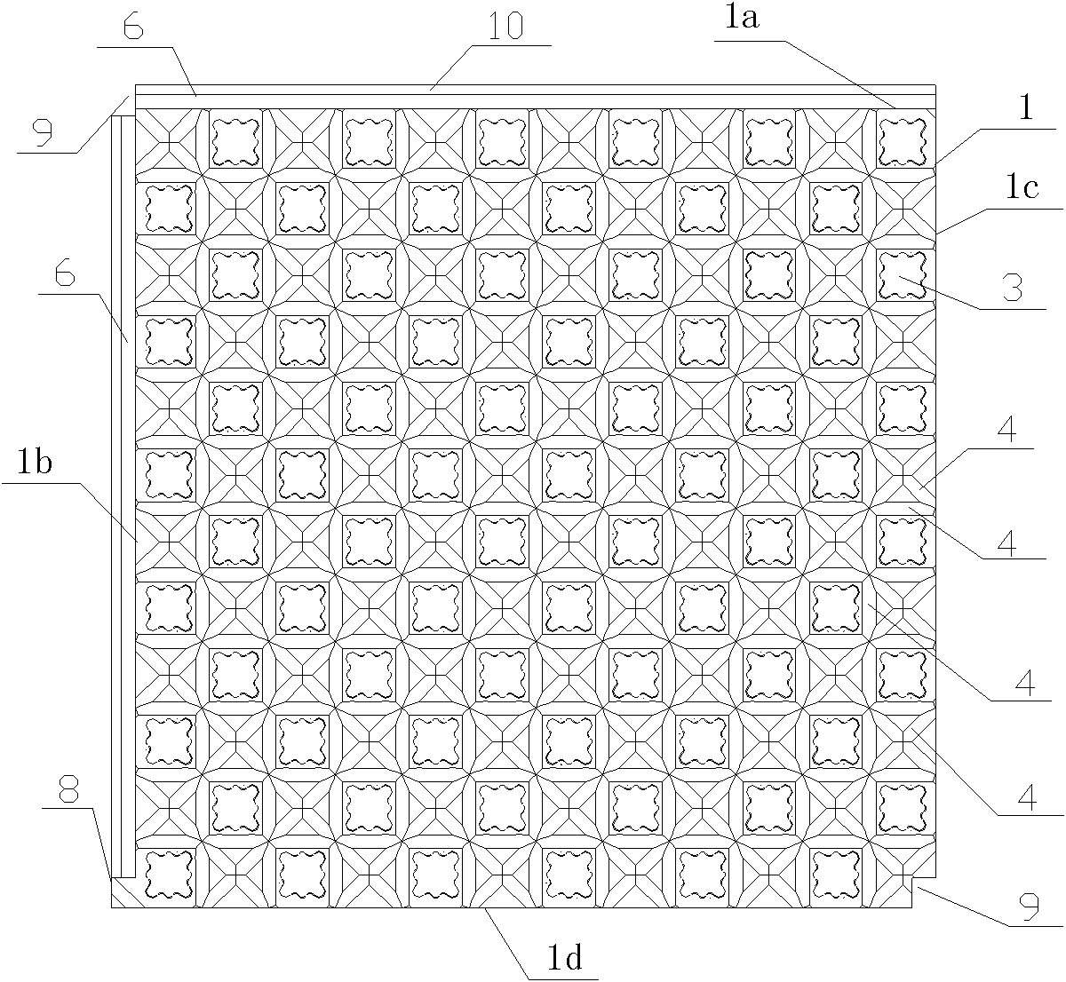
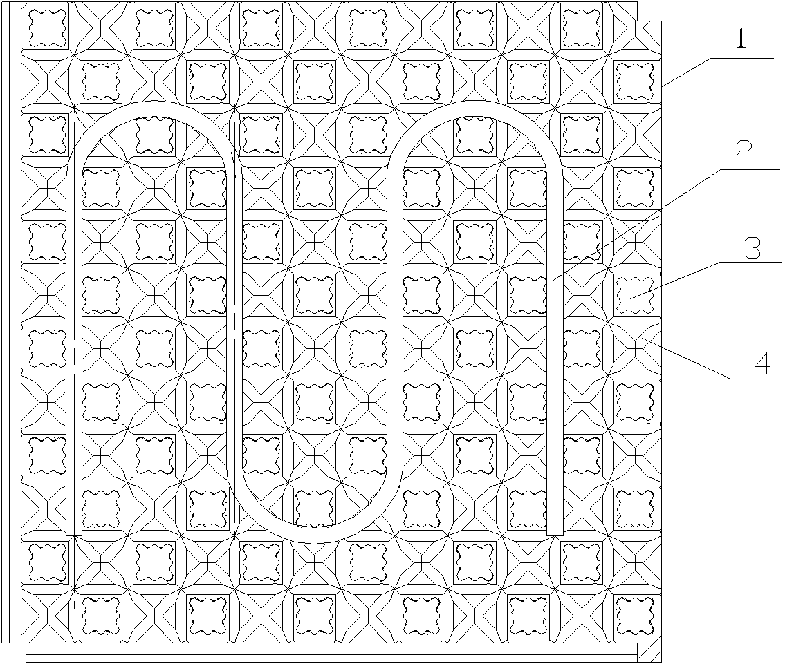
[0021] Such as Figure 1 to Figure 4 As shown, the floor heating insulation layer is first laid on the indoor cement floor, the floor heating pipeline 2 is laid on the floor heating insulation layer, and then a layer of cement is poured on it, and the indoor floor or tiles are laid on the cement.

[0022] Floor heating insulation layer comprises thermal insulation board 1, and the material selection EPS (expanded polystyrene) of thermal insulation board 1, for easy installation, the shape of thermal insulation board 1 is generally a square.

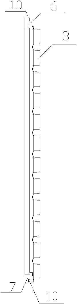
[0023] Several protrusions 3 are arranged on the front of the insulation board 1, the protrusions 3 are regularly arranged on the insulation board 1, the protrusions 3 and the insulation board 1 are integrally foamed, and the protrusions 3 can improve the mechanical strength of the insulation board 1, The carrying capacity is also greatly improved. Such as figure 2 As shown, the floor heating pipe 1 is directly stuck between the protru...

Embodiment 2

[0033] As shown in Figure 6, several second grooves 5 are arranged on the first groove 4, the second grooves 5 are arranged at the intersection of each first groove 4, and the bottom surface of the second groove 5 is slightly lower On the bottom surface of the first groove 4 next to it, the width of the second groove 5 is slightly larger than the width of the first groove 4, and the second groove 5 can be polygonal, square or circular. shaped structure. After pouring cement on the heating pipe 2, the cement in the second groove 5 can flow to the bottom of the heating pipe 2, that is, the whole heating pipe 2 is surrounded, and after the cement is solidified, the cement here forms a pipe. The function of the clip makes the floor heating pipeline 2 more firmly fixed.


PUM


Abstract

The invention relates to a ground-heating thermal insulation layer, which comprises thermal insulation boards, wherein a plurality of bumps which are used for clamping and fixing ground-heating pipelines are integrally arranged on the front surface of the thermal insulation boards; a first groove which is used for partially accommodating the full length of the ground-heating pipelines is arranged among the bumps along the laying direction of the ground-heating pipelines; the upper plane of each bump is slightly higher than the top of each ground-heating pipeline; and lapping structures which are adjacent to the thermal insulation boards and mutually and fixedly arranged are arranged on the four sides of the thermal insulation boards. The ground-heating pipelines can be directly clamped among the bumps, not only the material cost is reduced, but also the efficiency can be improved, and the operation is simple and convenient. The adjacent thermal insulation boards are installed and fixed by the closer lapping structures, and heat can be prevented from losing from gaps of the thermal insulation layers to the greatest possibility, and the thermal insulation efficiency is improved.

Description

technical field [0001] The invention relates to a floor heating insulation layer, which belongs to the technical field of floor heating. Background technique [0002] When laying floor heating equipment, a floor heating insulation layer is needed between the ground and the floor in the room to prevent the heat of the floor heating pipe from transferring to the ground. The pipe is fixed on the floor heating insulation layer, and a layer of cement is poured on it. Lay floors or tiles over cement. The insulation layer is generally made of EPS and other heat insulation materials. At present, the structure of the floor heating insulation layer commonly used in the market is relatively simple. The floor heating pipes are fixed on the insulation layer with structural parts such as pipe clamps. The fixing method is complicated and the cost is correspondingly increased. , and the floor heating insulation layer is laid on the ground by splicing two insulation panels, so that heat wil...

Claims


Application Information

Patent Timeline
Patent Type & Authority Applications(China)
IPC IPC(8): E04F15/10E04B1/80
Inventor 张宝利罗伟刘钊
Owner QING DAO HAIJING PACKING MATERIALS
Why Eureka
Try Eureka