Improved heat-dissipating structure

A technology of heat dissipation structure and heat dissipation part, which is applied in the directions of heat exchange equipment, heat exchanger shell, indirect heat exchanger, etc. Effect

Active Publication Date: 2012-02-01
ASIA VITAL COMPONENTS SHENZHEN CO LTD
View PDF7 Cites 12 Cited by
  • Summary
  • Abstract
  • Description
  • Claims
  • Application Information

AI Technical Summary

Problems solved by technology

[0007] 1. Inconvenient processing;
[0008] 2. Unable to achieve thinning;
[0009] 3. High cost;
[0010] 4. Time-consuming

Method used


Image

  • Improved heat-dissipating structure
  • Improved heat-dissipating structure
  • Improved heat-dissipating structure

Examples


Embodiment Construction

[0054] The above-mentioned purpose of the present invention and its structural and functional characteristics will be described according to the preferred embodiments of the accompanying drawings.

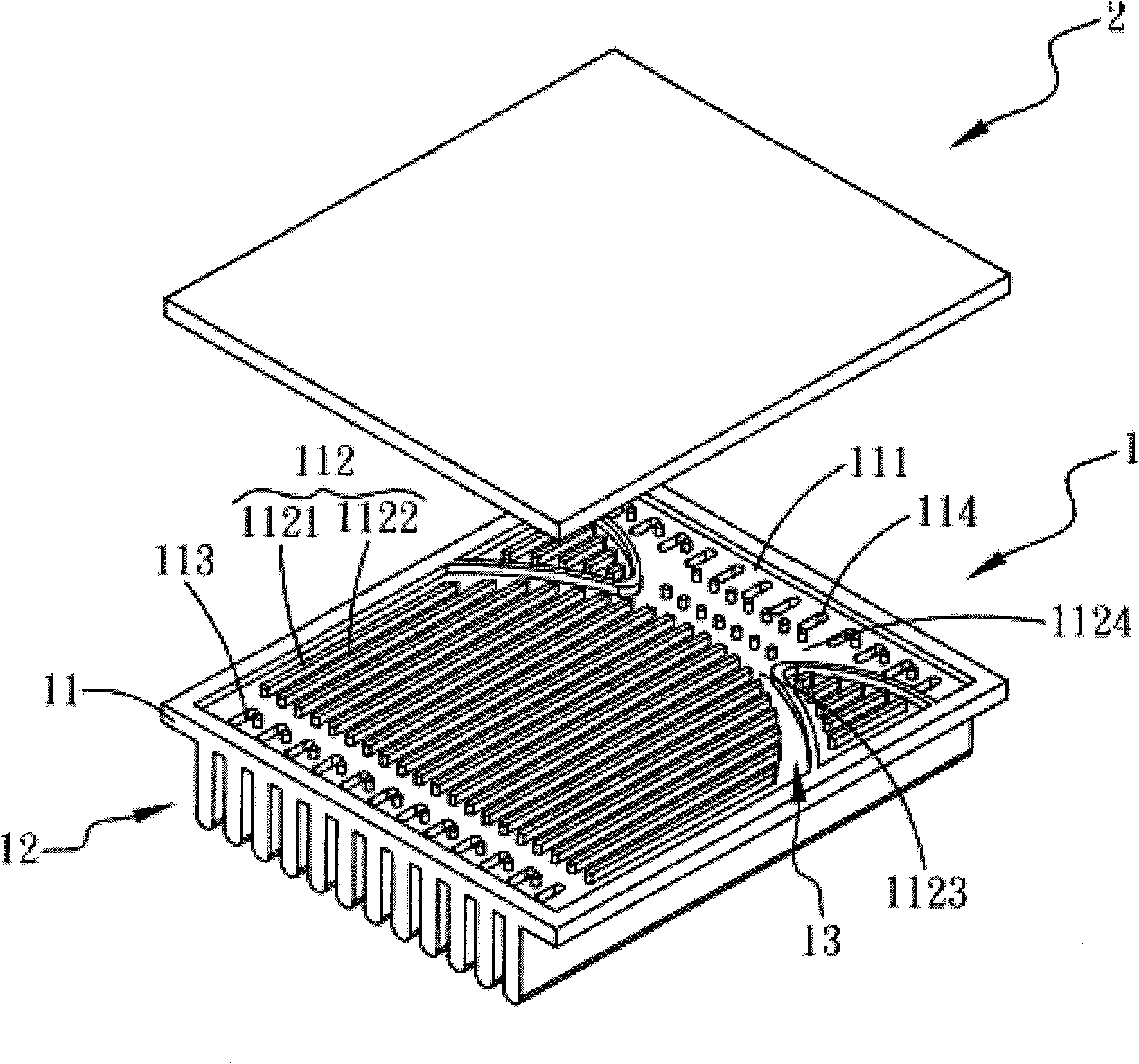
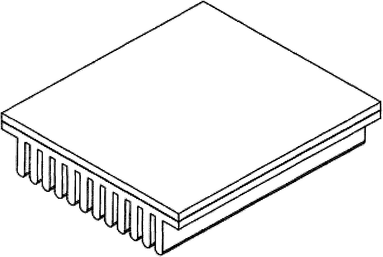
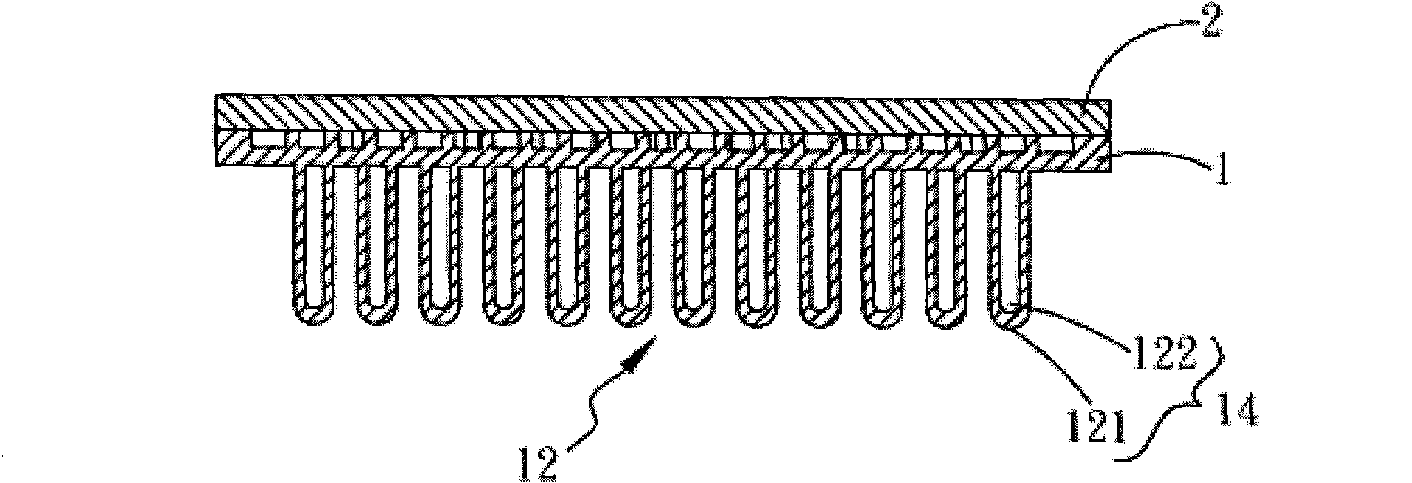
[0055] Please refer to Figures 1, 2, and 3, which are three-dimensional disassembly, assembly and cross-sectional views of a preferred embodiment of the improved heat dissipation structure of the present invention. As shown in the figure, the heat dissipation structure includes: a body 1 and a bottom plate 2;

[0056] The body has a heat absorbing portion 11 and a heat dissipating portion 12. The heat absorbing portion 11 has a chamber 111 inside, and the chamber 111 has a plurality of first guide portions 112, a first communication hole group 113 and a second The communication hole group 114, the first guide part 112 is composed of a plurality of first guide bodies 1121 arranged at intervals, at least one first flow channel 1122 is formed between the first guide bodies 1121, at lea...


PUM


Abstract

The invention provides an improved heat-dissipating structure comprising a body and a bottom plate, wherein the body is provided with a heat absorption part and a heat dissipation part; the heat dissipating part is provided with a plurality of heat-dissipating fins; the heat absorption part is provided with a cavity; the cavity is provided with a plurality of first guiding parts, a first interconnected pore group and a second interconnected pore group; each first guiding part is composed of a plurality of guiding objects which are arranged at intervals; at least one first channel is formed between the guiding objects; at least one end of the first channel is a free end and is connected with a free area; each first guiding part and each first channel can jointly define an evaporation area,; the interior of each heat-dissipating fin is provided with a second channel and can define a condensation area together with the heat-dissipating fin; the first and second interconnected pore groups are communicated with the evaporation area and the condensation area; the bottom plate correspondingly covers the cavity; and a low pressure end is generated in the condensation area by virtue of a proper pressure-reducing design to form pressure gradient required by driving gas-water circulation in a heat dissipating structure, so that a work fluid can be driven to transfer heat without any capillary structure.

Description

technical field [0001] The invention relates to an improved heat dissipation structure, especially an improved heat dissipation structure that can drive a working fluid to transfer heat without any capillary structure, and greatly reduces manufacturing costs. Background technique [0002] In recent years, with the vigorous development of the electronic semiconductor industry, the progress of process technology, and under the trend of market demand, electronic equipment has gradually moved towards thinner and smaller shapes. It is unabated. For example, in the actual operation of communication chassis and heat exchangers / devices for household or industrial use, there are many electronic components inside which generate heat, among which the electronic crystals or components that perform calculations generate the most heat. The heat sink composed of chips and fans provides heat dissipation function and plays an important role in protecting the electronic components, so that t...

Claims


Application Information

Patent Timeline
Patent Type & Authority Applications(China)
IPC IPC(8): F28D15/02F28F9/00
Inventor 江贵凤张始伟
Owner ASIA VITAL COMPONENTS SHENZHEN CO LTD
Why Eureka
Try Eureka