Liquid applicator vessel

A liquid material and delivery technology, which is applied in household containers, cosmetic containers, cosmetic powder containers, etc.

Inactive Publication Date: 2012-02-01
MITSUBISHI PENCIL CO LTD
View PDF7 Cites 5 Cited by
  • Summary
  • Abstract
  • Description
  • Claims
  • Application Information

AI Technical Summary

Problems solved by technology

Although the container is designed to reduce the number of parts in this way, there is still room fo

Method used


Image

  • Liquid applicator vessel
  • Liquid applicator vessel
  • Liquid applicator vessel

Examples


Embodiment Construction

[0031] Embodiments of the present invention will be described below with reference to the drawings.

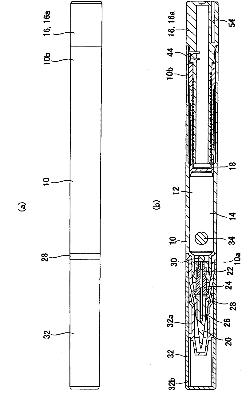
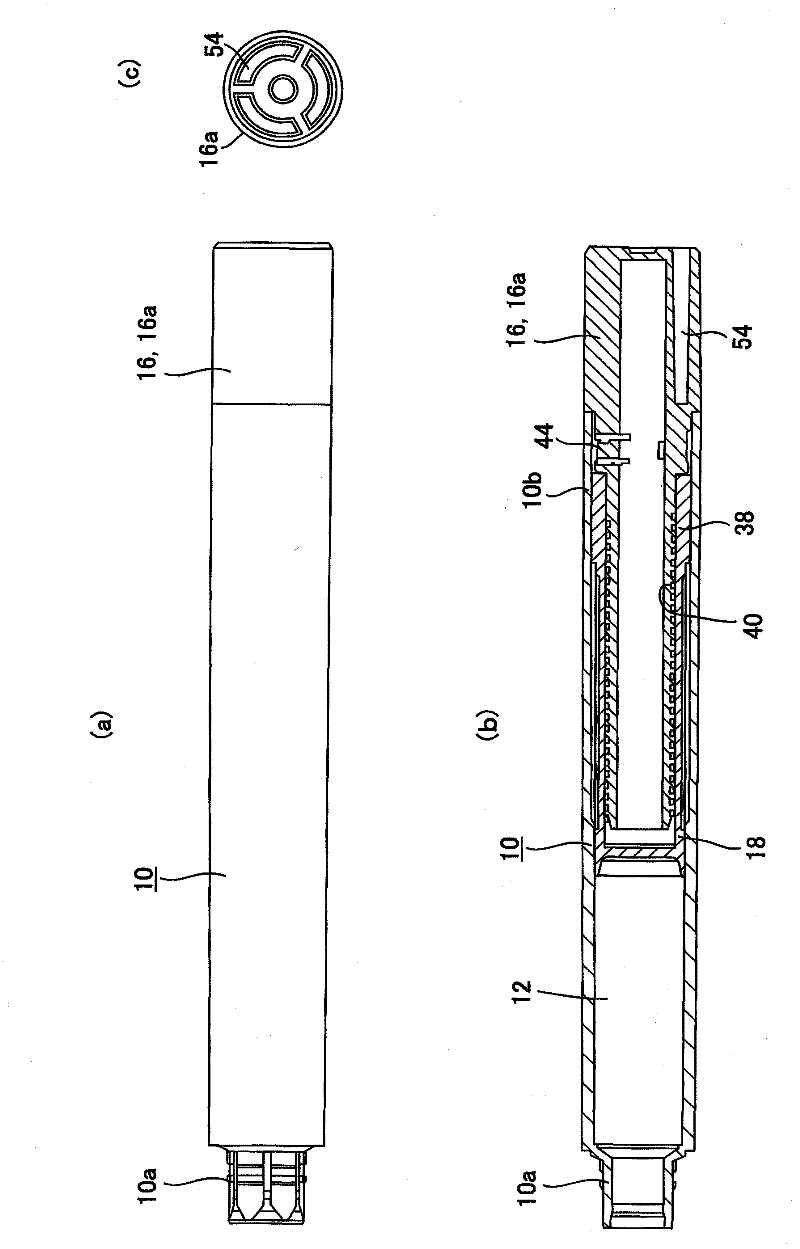
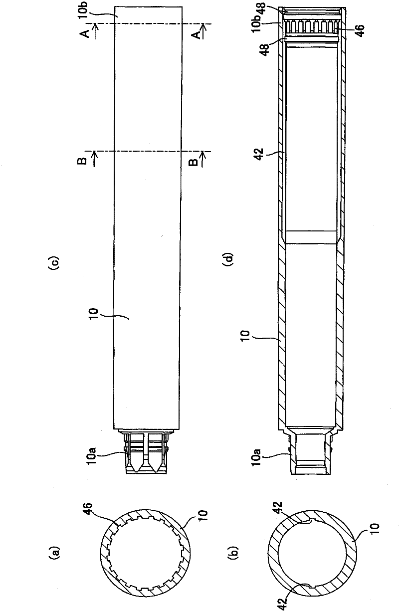
[0032] Figure 1 to Figure 5 are explanatory diagrams of the liquid material feeding container according to the embodiment of the present invention, and in these drawings, parts assigned the same reference numerals denote the same components.

[0033] Such as figure 1 and figure 2 As shown, the liquid feeding container of the present embodiment is a liquid material feeding container as follows: the liquid content 14 is accommodated in the storage portion 12 provided on the cartridge body 10, and the rotating member 16 is rotated from the rear end of the cartridge body 10 The operating part 16a exposed from the part 10b rotates relative to the cylinder body 10 to advance the piston 18 in the storage part 12 and feed the content 14 to the front of the cylinder body 10. The liquid material feeding container is composed of three parts, namely: Cartridge body 10 , rotating eleme...


PUM


Abstract

Disclosed is a liquid applicator vessel, the cost of which is reduced while maintaining the same impression from use as current products by decreasing the number of parts while maintaining the quality demanded from a rotary applicator vessel, and enabling assembly using a simple method. In the liquid applicator vessel, sealing sections (18a, 18a) formed on the outer circumference of the front section of a piston (18) make sliding contact with the inner wall of an enclosed section (12) of a main shaft (10), and additionally a tubular portion (18b) is formed having a female screw section (38) on the inner circumference and a pair of protrusions (36) configured from rib-shaped protrusions protruding radially outward from the outer circumference of the back section of the piston (18). A male screw section (40) which is threaded with the female screw section (38) of the aforementioned tubular portion (18b) is formed on the outer circumferential surface of the front section extending forward from the operating section (16a) of a rotating body (16). The space of the enclosed section (12) is formed towards the front of the aforementioned main shaft (10), and towards the back, grooves (42) which engage the protrusions (36) of the aforementioned tubular portion (18b) are formed along the axial direction.

Description

technical field [0001] The present invention relates to a liquid material feeding container that accommodates liquid materials such as liquid or fluid cosmetics or medicines in a storage portion of a barrel body and that is fed by rotating the rear end. The feeding operation supplies the stored liquid material to the coating unit. Background technique [0002] In a conventional general rotary liquid material feeding container, as shown in the example of Japanese Patent Application Laid-Open No. 9-322819 (Patent Document 1), etc., the feeding mechanism section includes six parts: a cylinder body, a piston, a threaded rod , a thread socket, a feeding element, and a crown (crown), and the feeding mechanism part is configured to be capable of feeding operation by the feeding element (rotation operation of the feeding element via the crown relative to the thread socket) An appropriate amount of liquid material is fed to the coating element. [0003] However, in the above-mentio...

Claims


Application Information

Patent Timeline
IPC IPC(8): A45D34/04B05C17/01B65D83/00
CPCA45D2200/055A45D34/04A45D34/042A45D40/205A45D40/20
Inventor 福本刚生住吉聪远藤满
Owner MITSUBISHI PENCIL CO LTD
Why Eureka
Try Eureka