Charge device

A charging device and electrode technology, applied in electrostatic separation, electrode structure, external electrostatic separator, etc., can solve the problems of high particle loss and low charging efficiency

Active Publication Date: 2012-02-08
TSINGHUA UNIV
View PDF4 Cites 6 Cited by
  • Summary
  • Abstract
  • Description
  • Claims
  • Application Information

AI Technical Summary

Problems solved by technology

[0003] Aiming at the shortcomings of low charging efficiency and high particle loss of the existing charging device mentioned in the above background technology, the present invention proposes a charging device

Method used


Image

  • Charge device
  • Charge device
  • Charge device

Examples


Embodiment Construction

[0013] The preferred embodiments will be described in detail below in conjunction with the accompanying drawings. It should be emphasized that the following description is only exemplary and not intended to limit the scope of the invention and its application.

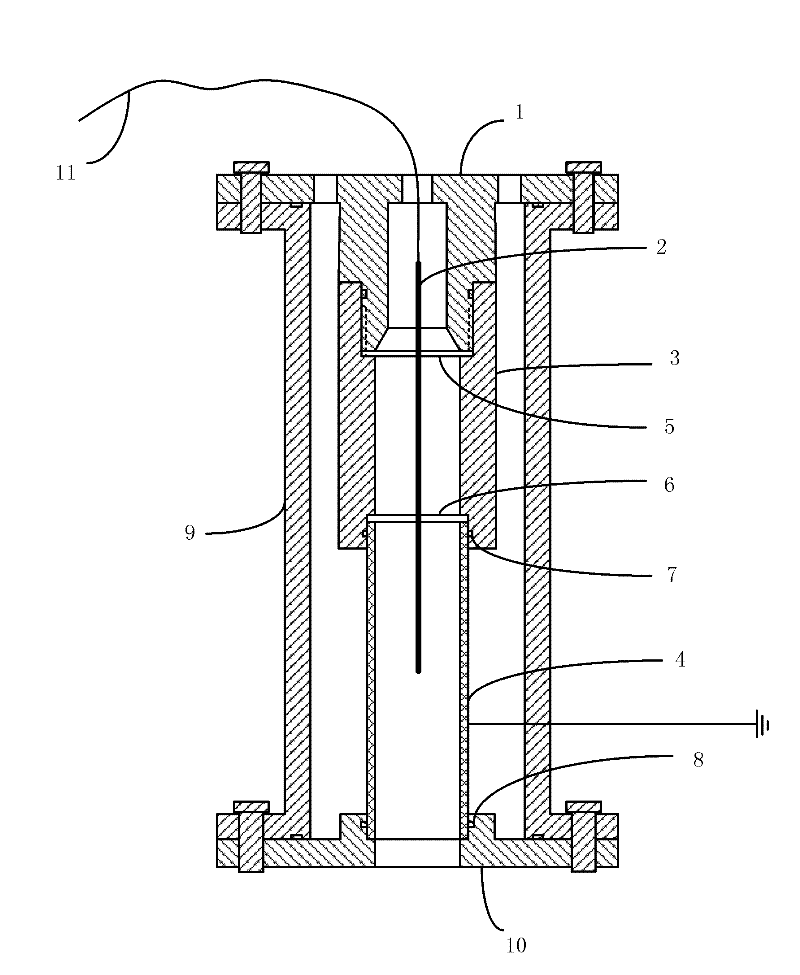
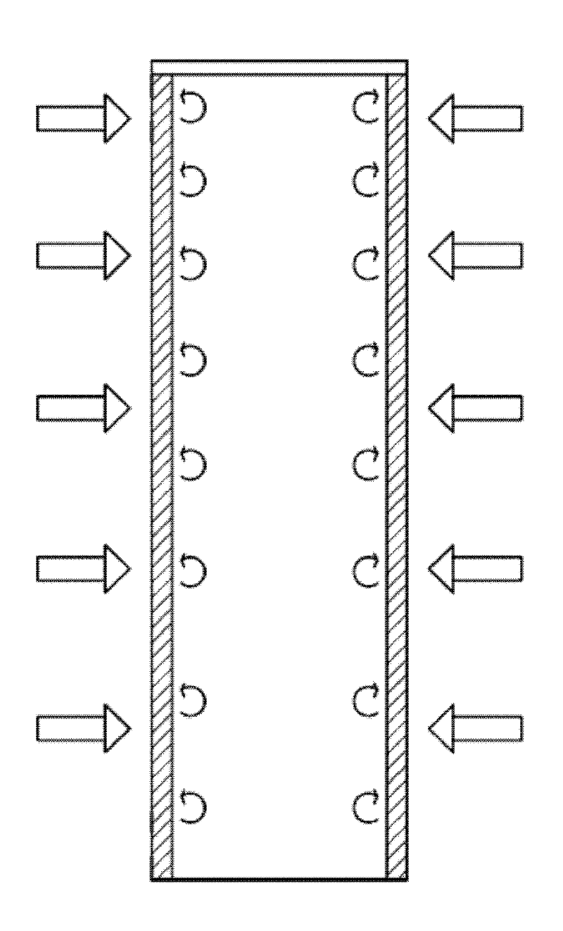
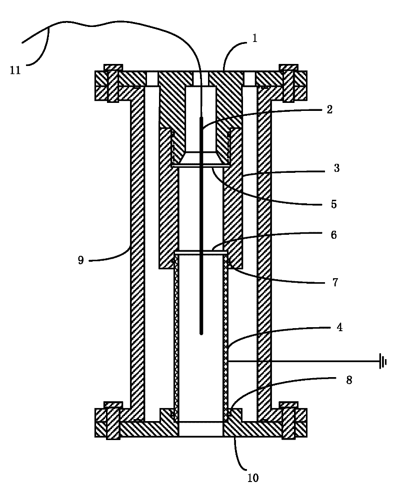
[0014] The device of the invention utilizes corona discharge to generate a corona electric field, forms a large number of air ions around the discharge needle, and can fully charge high-concentration particles in the dust-laden airflow in the electric field. The lateral airflow introduced from the upper cover is blown to the electric field through the polar plate, which effectively inhibits the movement of particles to the polar plate, significantly reduces the deposition of particles on the polar plate, improves the charging efficiency, and reduces the loss of particles.

[0015] The inventive device such as figure 1 As shown, including upper cover, discharge needle, inner sleeve, pole plate, first electrode fixing p...


PUM


Abstract

The invention discloses a charge device, belonging to the technical field of particle change. The device comprise an upper cover, a discharging needle, an inner sleeve, a polar plate, a first electrode fixing sheet, a second electrode fixing sheet, a first O-shaped sealing ring, a second O-shaped sealing ring, an insulating shell, a lower cover and a lead. In the charge device, particles are charged by performing corona discharge, and lateral air inflow of the polar plate is adopted, so that the sedimentation of particles on the wall surface of the polar plate is reduced, the charging efficiency of the particles is increased, and particle loss is reduced.

Description

technical field [0001] The invention belongs to the technical field of particle charging, and in particular relates to a charging device. Background technique [0002] Micron and submicron particles have many unique physical, chemical and biological properties. They are widely used in materials synthesis, biotechnology, semiconductor manufacturing, nanocomposites and ceramics, pharmaceutical production, instrumentation and pollution control technology. In these fields, it is often encountered that particles are charged first and then enter other process links. Particle charging technology is a basic and very important technology. There are generally two charging mechanisms in particle charging technology: diffusion charging and field charging. The main charging mechanism for particles with a diameter of less than 1 micron is diffusion charging, while the main charging mechanism for particles with a diameter of more than 1 micron is field-induced charging. Since the partic...

Claims


Application Information

Patent Timeline
Patent Type & Authority Applications(China)
IPC IPC(8): B03C3/04B03C3/43B03C3/47
Inventor 宋蔷涂扬赓姚强
Owner TSINGHUA UNIV
Why Eureka
Try Eureka