

Quick assembly disengaging device
A demolition device and quick-installation technology, applied in lifting devices, multi-purpose hand tools, crowbars, etc., can solve problems such as loss of life and property, delay in rescue time, etc.
Inactive Publication Date: 2012-02-08
刘于颇
View PDF10 Cites 3 Cited by
- Summary
- Abstract
- Description
- Claims
- Application Information
AI Technical Summary
Problems solved by technology
[0002] On May 12, 2008, a major earthquake occurred in Wenchuan. A large number of houses collapsed, lives and property suffered heavy losses, and a large number of people were buried under the ruins. , shovels and other crude tools rescued a large number of buried people. Due to the inability to use large machinery, some soldiers even ground their bones... Sometimes it was only because of the barrier of a prefabricated board that the precious rescue time was delayed.
Method used
View moreImage
Smart ImageViewing Examples

Examples
Embodiment Construction
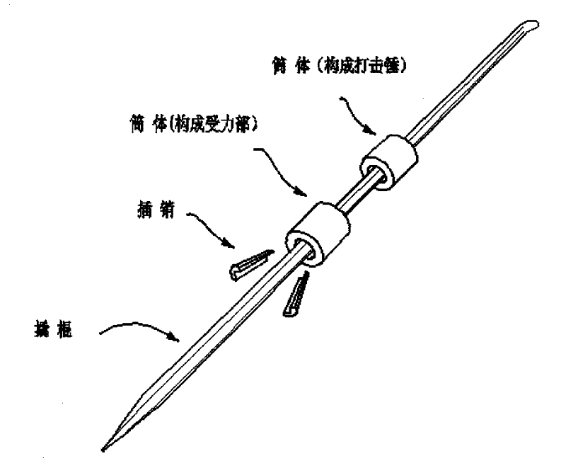
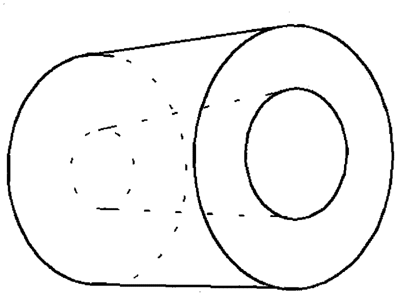
[0008] 1. From the tip of the crowbar, install the image 3 Shown are two perforated metal cylinders with large mouths facing rearward.
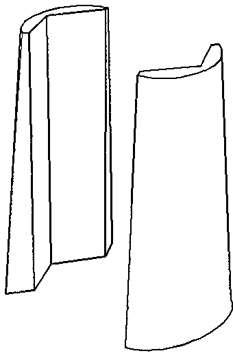
[0009] 2. Will figure 2 The two bolts shown are inserted into the gap between the second cylinder and the crowbar and tapped tightly (six flute, square or round crowbars need correspondingly shaped bolts).
[0010] 3. Swing the unfixed cylinder in the direction of the crowbar and hit it.
Login to View More PUM
 Abstract
The invention discloses a quick assembly disengaging device. Two kinds of parts, namely a bolt and cylinders are assembled on a standard crowbar; and by a self-locking principle, one cylinder is fixed and the other cylinder is used as a peening hammer to form the disengaging device. The disengaging device has the function of the crowbar, becomes the disengaging device once assembled, and can disengage on special parts which cannot be excessively disturbed or have narrow spaces, wherein one cylinder is a metal cylinder, the middle of the cylinder is provided with a taper hole having a larger end and a smaller end, the slope of the taper is kept consistent with the slope of the bolt, a self-locking angle can be reached, and after the cylinder is sleeved in the crowbar, the bolt is inserted into a gap formed between the larger hole and the crowbar, and a stress body is formed after the bolt is tightly knocked; and the other cylinder is used as the peening hammer and moves along the crowbar vertically for peening.
Description
Technical field [0001] The invention belongs to the category of tools. It is used in rescue sites where large machinery, electric and pneumatic tools are inconvenient to operate. Background technique [0002] On May 12, 2008, a major earthquake occurred in Wenchuan. A large number of houses collapsed, lives and property suffered heavy losses, and a large number of people were buried under the ruins. A large number of buried people were rescued with simple tools such as shovels, shovels, etc. Because large machinery could not be used, some soldiers even ground their hands to the bone... Sometimes it was only because of a prefabricated board that the precious rescue time was delayed. From this, I came up with the idea of inventing a simple and efficient rescue tool for soldiers - quick release device. Contents of the invention [0003] The quick-loading demolition device is assembled on a standard crowbar with two parts - the latch and the cylinder. Using the self-lockin...
Claims
Login to View More Application Information
Patent Timeline
 IPC IPC(8): B25F1/00B25D1/16B66F15/00
Inventor刘于颇
Owner刘于颇