Template pushing device for conveying template

A push device and template technology, applied in the direction of conveyors, transportation and packaging, etc., can solve the problems of low work efficiency, high labor intensity, inability to meet large batches, automatic production, etc., achieve labor-saving operation, improve work efficiency, and save production the effect of time

Inactive Publication Date: 2012-02-08
张家港市玉龙科技板材有限公司
View PDF8 Cites 14 Cited by
  • Summary
  • Abstract
  • Description
  • Claims
  • Application Information

AI Technical Summary

Problems solved by technology

At present, a commonly used method of transferring templates is the traditional manual loading. The operator lifts both sides of the board and puts it on the loading device, and then the template is sent to the belt conveyor table of the production line by the loading device; Or the workers directly put the template on the belt conveyor table of the production line. This method mainly exists in small-scale factories. Its disadvantages are: high labor intensity, low work efficiency, and cannot meet the needs of large-scale and automated production.

Method used


Image

  • Template pushing device for conveying template
  • Template pushing device for conveying template
  • Template pushing device for conveying template

Examples


Embodiment Construction

[0017] The technical solutions of the present invention will be further described below in conjunction with the accompanying drawings and specific embodiments.

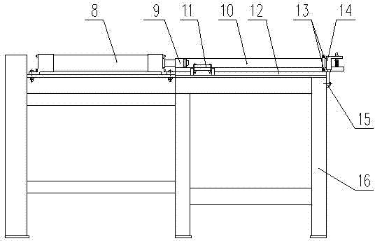
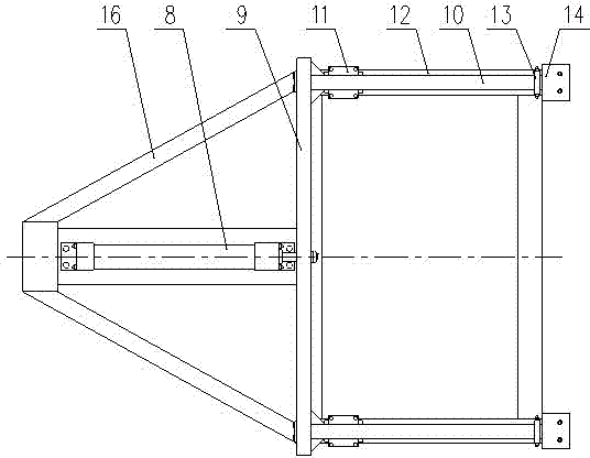
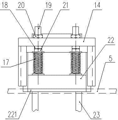
[0018] Such as figure 1 , figure 2 As shown, the template pushing device for conveying templates according to the present invention includes: a push pedal bracket 16, on which a push pedal cylinder 8 is fixedly installed. In this embodiment, the piston rod of the push pedal cylinder 8 It is fixedly connected with a cross bar 9, and the two ends of the cross bar 9 are respectively fixedly connected with a push rod 10, and each push rod 10 is fixedly connected with a linear guide rail slider 11, and the linear guide rail slider 11 is arranged on the linear guide rail 12 , and can slide back and forth on the linear guide rail 12, the linear guide rail 12 is fixed on the push pedal support 16, and a limit device that can limit the push pedal cylinder stroke is also provided on the push pedal support 16, and it is useful...


PUM


Abstract

The invention discloses a template pushing device for conveying a template. The device comprises a push plate bracket, wherein a push plate cylinder is fixedly arranged on the push plate bracket; the device is characterized in that: a piston rod of the push plate cylinder is connected with a push rod; the push rod is fixedly connected with a linear guide rail slide block; the linear guide rail slide block is arranged on a linear guide rail and can slide back and forth on the linear guide rail; the linear guide rail is fixed on the push plate bracket; the push plate bracket is also provided with a limiting device which can limit travel of the push plate cylinder; and the front end of the push rod is provided with a pusher device for pushing the template. The device has the advantages of meeting requirements of continuous production, facilitating continuous pushing of the template into a specified position, saving labor in operation, saving production time and increasing working efficiency. The device can be applied to producing a glass magnesium board in building decoration material industry.

Description

technical field [0001] The invention relates to production equipment of glass magnesium boards in the building decoration material industry, and in particular to a template pushing device used in a glass magnesium board production line for conveying templates. Background technique [0002] The glass magnesium industry is a new industry in China, which started relatively late, but has developed rapidly in recent years. Glass magnesium material is an emerging building material in recent years. It has become an indisputable fact that glass magnesium replaces wood, glass magnesium instead of steel, and glass magnesium instead of cement in some projects. In terms of cost, molding, operation, performance, etc., glass magnesium Materials play their unique advantages. At present, glass magnesium products such as fireproof boards, ventilation ducts, lightweight partition walls, logistics trays, and fire door core panels in the market occupy a large market share. In recent years, gla...

Claims


Application Information

Patent Timeline
Patent Type & Authority Applications(China)
IPC IPC(8): B65G25/12
Inventor 李洪华李钦奉王筱蓉蔡运迪张礼军朱凤梅
Owner 张家港市玉龙科技板材有限公司
Why Eureka
Try Eureka