Speed reducing shaft clutch for washing machine

A deceleration shaft and clutch technology, applied to clutches, non-mechanical drive clutches, washing machines with containers, etc., can solve the problems of inflexible control, not being too fast, complex structure, etc., and achieve accurate control, not easy to disengage, and small size Effect

Inactive Publication Date: 2012-02-08
CHANGZHOU XINYA ELECTROMOTOR
View PDF4 Cites 16 Cited by
  • Summary
  • Abstract
  • Description
  • Claims
  • Application Information

AI Technical Summary

Problems solved by technology

[0003] The main job of the washing machine is to drive the pulsator to rotate by the main shaft, agitate the water flow and rotate the clothes to achieve the purpose of washing the clothes. Since the clothes cannot be strongly rubbed, the speed of the pulsator is generally limited to a certain extent and cannot be too fast. Due to the limitation of space, most of the driving motors directly drive the main shaft to drive the pulsator. Therefore, most of the current washing machines use low-speed and high-torque motors, which has caused certain limitations in the selection of driving motors; A clutch is installed in the washing machine, and most of the existing internal clutches of the washing machine use the cooperation of ratchet, pawl and clutch lever. This clutch device has disadvantages such as relatively complicated structure, large volume, and inflexible control.

Method used


Image

  • Speed reducing shaft clutch for washing machine
  • Speed reducing shaft clutch for washing machine
  • Speed reducing shaft clutch for washing machine

Examples


Embodiment Construction

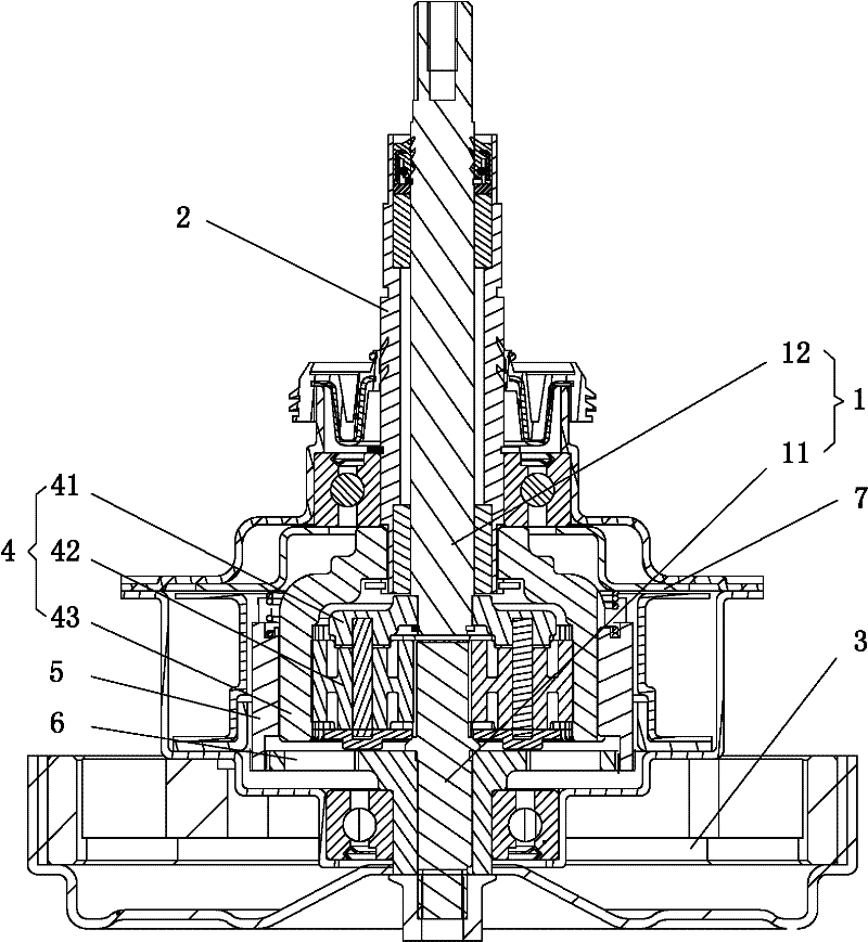
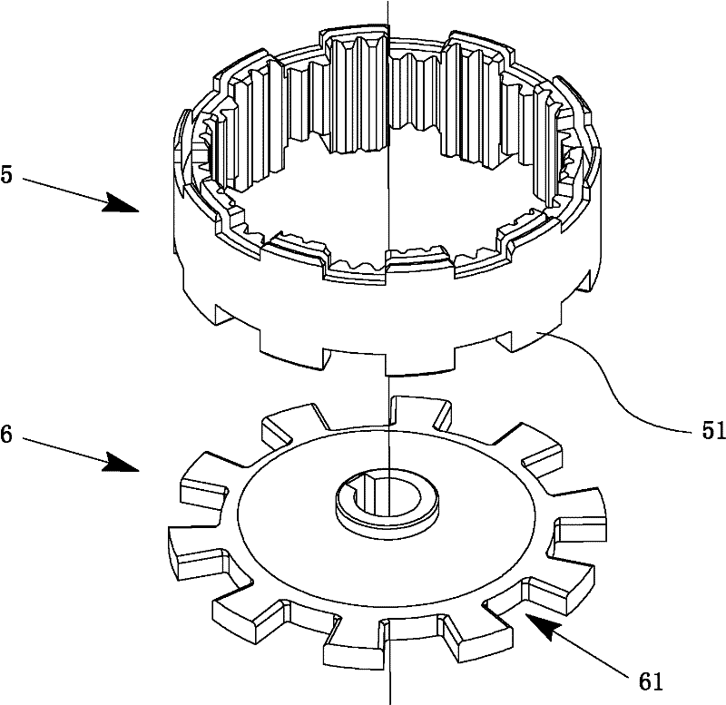
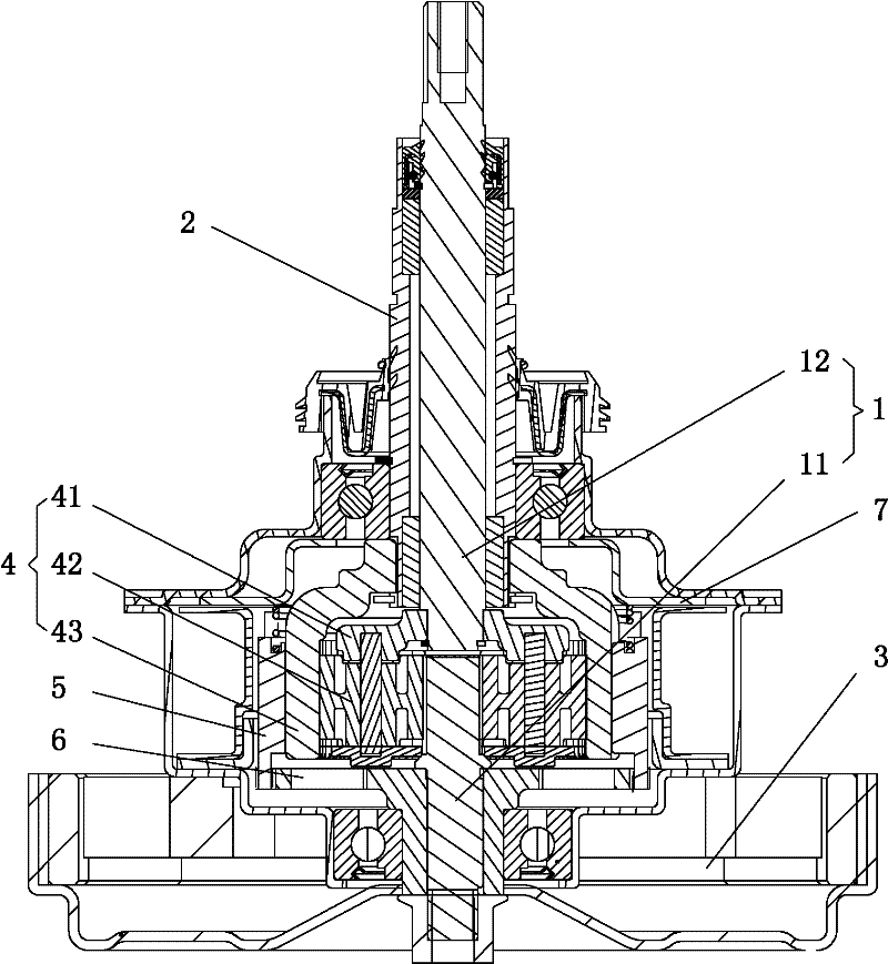
[0013] See figure 1 with figure 2 , the present invention has a drive shaft 1 and a drive shaft sleeve 2, the drive shaft 1 is rotatably arranged in the drive shaft sleeve 2, and the drive motor 3 is fixedly connected thereunder; it is characterized in that: the drive shaft 1 has a drive shaft arranged coaxially in the up and down direction Shaft 11 and transmission shaft 12, drive shaft 11 is connected with drive motor 3, planetary gear assembly 4 is arranged outside it, planetary gear assembly 4 has planetary gear cage 41, is arranged on planetary gear cage 41, and is in phase with drive shaft 11 The meshing planetary gear 42 and the planetary outer gear ring 43 arranged on the outer ring of the planetary gear 42 and meshed with the planetary gear 42, the planetary gear outer gear 43 is connected with the transmission shaft 12, and the outer planetary gear 43 is socketed Toothed clutch ring 5, spline fit between the toothed clutch ring 5 and the outer ring gear 43 of the p...


PUM


Abstract

The invention relates to a speed reducing shaft clutch for a washing machine. The clutch is provided with a driving shaft and a driving shaft sleeve, wherein the driving shaft is provided with a secondary driving shaft and a transmission shaft which are coaxially arranged in the vertical direction; the secondary driving shaft is connected with a drive motor; a planet wheel component is arranged on the outer side of the secondary driving shaft, and is provided with a planet wheel retainer, a planet wheel which is arranged on the planet wheel retainer and is engaged with the secondary driving shaft and a planet wheel outer gear ring which is arranged on the outer ring of the planet wheel and is engaged with the planet wheel; the planet wheel outer gear ring is connected with the transmission shaft; a tooth-shaped clutch ring is sleeved on the outer side of the planet wheel outer gear ring, is in spline fit with the planet wheel outer gear ring and is in sliding connection with the planet wheel outer gear ring in the vertical direction; a slotted gear is arranged at the lower end of the tooth-shaped clutch ring; a slot disc which is fixedly connected with the secondary driving shaft is arranged below the tooth-shaped clutch ring; a slot which is matched with the slotted gear at the lower end of the tooth-shaped clutch ring is formed on the slot disc; and an electromagnetic coil is arranged above the tooth-shaped clutch ring. The speed reducing shaft clutch can be suitable for a high-rotating-speed motor, has a compact structure, a reasonable design and high practicability and is accurately controlled.

Description

technical field [0001] The invention relates to a washing machine component, in particular to a deceleration shaft clutch for a washing machine. Background technique [0002] Washing machine is an indispensable household appliance in life. With the continuous advancement of science and technology and the improvement of people's living standards, people have higher and higher requirements for washing machines. [0003] The main job of the washing machine is to drive the pulsator to rotate by the main shaft, agitate the water flow and rotate the clothes to achieve the purpose of washing the clothes. Since the clothes cannot be strongly rubbed, the speed of the pulsator is generally limited to a certain extent and cannot be too fast. Due to the limitation of space, most of the driving motors directly drive the main shaft to drive the pulsator. Therefore, most of the current washing machines use low-speed and high-torque motors, which has caused certain limitations in the select...

Claims


Application Information

Patent Timeline
Patent Type & Authority Applications(China)
IPC IPC(8): D06F17/08F16D27/09F16H1/28
Inventor 胡义明朱剑力陈昌宋庆章
Owner CHANGZHOU XINYA ELECTROMOTOR
Why Eureka
Try Eureka