Container holding apparatus

A container frame and gear technology, applied in the field of container frame devices for holding cans and cups, can solve the problems of complex mold structure, unstable and loose container support, improve processing and formability, and reduce manufacturing costs , the effect of stable switching operation

Active Publication Date: 2013-11-13
NIFCO INC
View PDF2 Cites 0 Cited by
  • Summary
  • Abstract
  • Description
  • Claims
  • Application Information

AI Technical Summary

Problems solved by technology

[0009] In the switching structure of Patent Document 1, since the bottom support member is rotated by the force of the spring in the state where the frame body protrudes from the housing, the bottom support member is switched from the non-support position to the support position, therefore, an urging mechanism is necessary. Or the spring parts used by the spring mechanism are prone to loosening due to the size of the spring pressure. Once there is vibration, the support of the container is likely to be unstable.
In addition, since the frame body resists the spring pressure and is embedded in the case together with the bottom support member, the initial assembly with the case is not good.
[0010] In contrast, in the switching structure of Patent Document 2, although there is no need for springs and the advantages of less looseness, since it is along the guide rails with curved parts formed on both inner sides of the housing, the frame body is separated from the housing. In the protruding state, the bottom supporting member is switched between the non-supporting position and the supporting position according to the guiding shape of the guide rail. Therefore, the structure of the mold for forming is complicated, the forming is troublesome, and the production cost is high.

Method used


Image

  • Container holding apparatus
  • Container holding apparatus
  • Container holding apparatus

Examples


Embodiment Construction

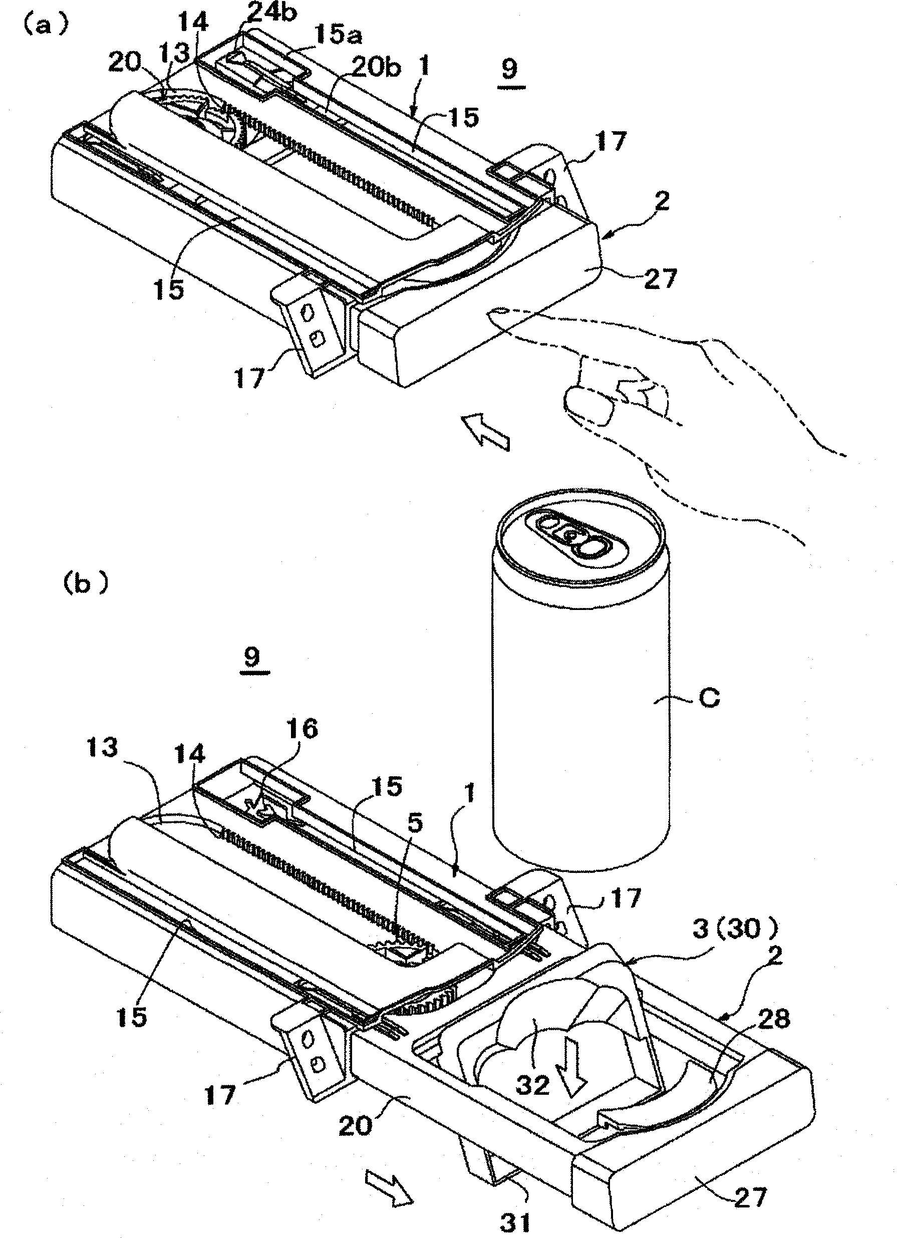
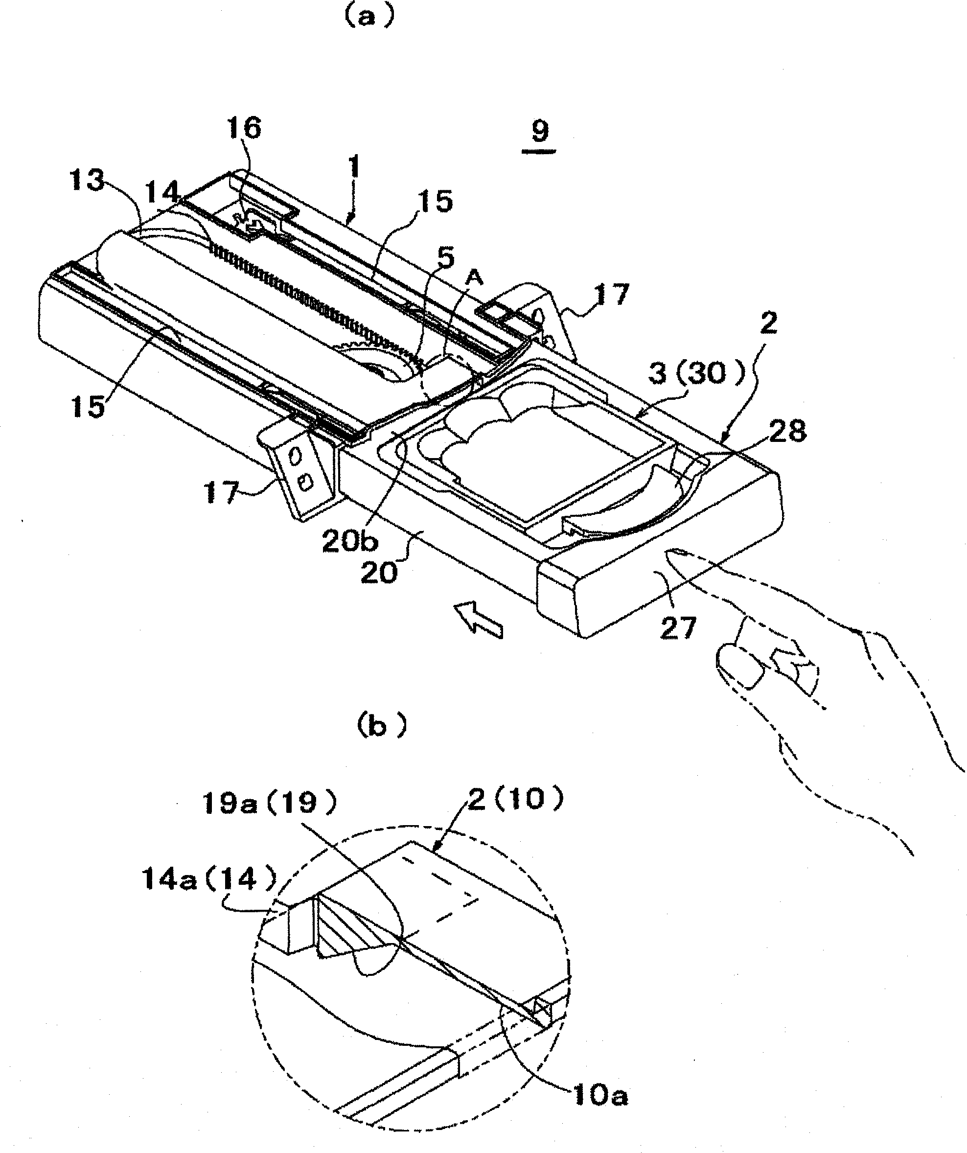
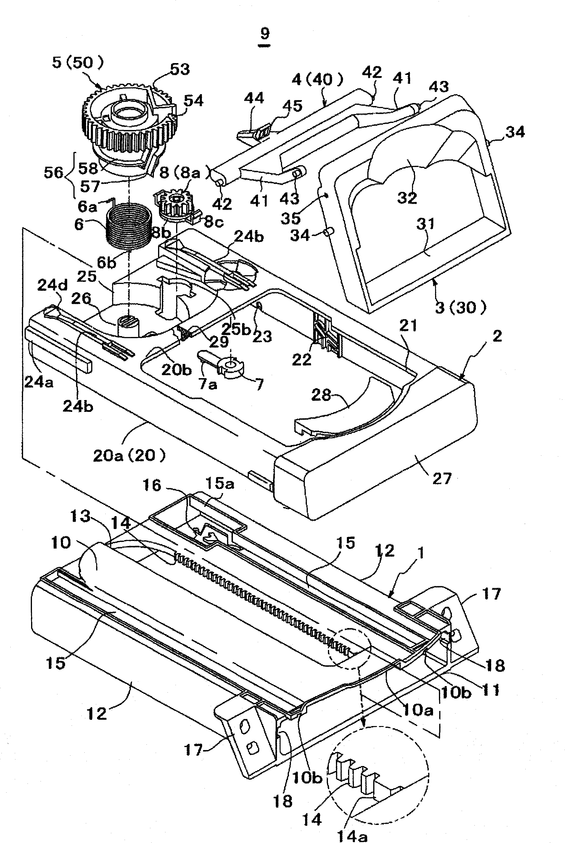
[0032] Refer to the following figure 1 (a)~ Figure 8 (c) A mode for explaining the present invention. In this description, details are described in the order of device structure, assembly, and operation.

[0033] (Device Structure) The container rack device 9 of the embodiment includes: a housing 1 having a rack 14; a rack body 2 movably assembled in the housing 1; a bottom support pivotally supported in a frame 21 of the rack body 2 Part 3; the gear 5 supported on the rear side recess 25 of the frame main body 2; the arm 4 that makes the bottom supporting part 3 and the gear 5 interlock; the force applying mechanism 6 of the coil spring structure arranged between the gear 5 and the recess 25; a push-push type latch mechanism (the pin portion 7 a of the rocker piece and the cam groove 16 ); and the rotation damper 8 .

[0034]The device structure is characterized in that the frame body 2 is assembled relative to the housing 1 so that it can move between the use position p...


PUM


Abstract

Proposed is a container holding apparatus comprising a case having a rack, a container holding body provided with a container support that surrounds a container and a gear, the container holding body capable of moving between a recessed position where the body is received in the case and an exposed position where the body is out of the case to be in use by means of the gear in cooperation with the rack, a bottom support member pivotably supported by the container holding body and movable between a non-supporting position near the container holding body and a supporting position where the bottom support member hangs down from the container holding body and where at least part of the bottom support member comes below the container support and a means for switching positions of the bottom support member between a supporting position and non-supporting position. The means for switching the positions has a cam arranged on the gear and a cam slide connected to the bottom support member to trace the cam.

Description

technical field [0001] The present invention relates to a container rack device for holding cans and cups, and particularly relates to a container rack device arranged in a car compartment, etc., with a rack main body entering and exiting relative to a housing, and having a bottom support member for receiving the bottom surface of the container. Background technique [0002] As the container holder device, as disclosed in Patent Document 1, it is provided with: a housing having a rack; Shelf body in the storage position and the use position pulled out of the housing; pivotally supported on the shelf body, switchable to an unsupported position close to the shelf body and hanging relative to the shelf body with at least a portion below the surrounding support a bottom support part in a support position; and a switching mechanism for switching the bottom support part into a support position and a non-support position. [0003] The above-mentioned bottom supporting member has a...

Claims


Application Information

Patent Timeline
Patent Type & Authority Patents(China)
IPC IPC(8): B60N3/00B60N3/10
CPCB60N3/102B60N3/106
Inventor 井爪友治
Owner NIFCO INC
Why Eureka
Try Eureka