Method for calibrating radial eccentricity parameters in milling process of flat head end mill

A flat end mill and parameter calibration technology, applied in metal processing mechanical parts, measuring/indicating equipment, metal processing equipment, etc., can solve problems such as unfavorable engineering applications and expensive milling force testing equipment.

Active Publication Date: 2012-02-15
NORTHWESTERN POLYTECHNICAL UNIV
View PDF2 Cites 10 Cited by
  • Summary
  • Abstract
  • Description
  • Claims
  • Application Information

AI Technical Summary

Problems solved by technology

[0019] The typical characteristics of the above documents are based on the measured milling force, the reliability of the calibration results depends on the

Method used


Image

  • Method for calibrating radial eccentricity parameters in milling process of flat head end mill
  • Method for calibrating radial eccentricity parameters in milling process of flat head end mill
  • Method for calibrating radial eccentricity parameters in milling process of flat head end mill

Examples


Embodiment 1

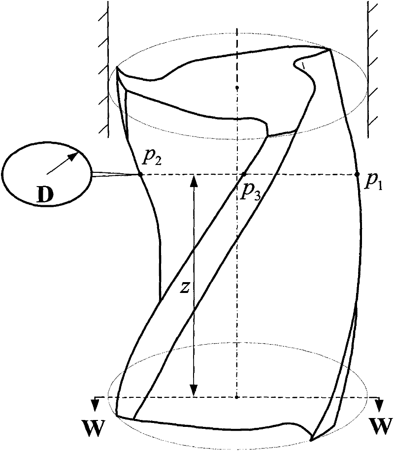
[0051] (1) Select the parameters of the end mill: the tool radius R is 8mm, the helix angle β is 30 degrees, and the number of tool teeth is N f is 3, assuming that the milling cutter is mounted on a three-axis vertical milling machine.

[0052] (2) Select N=4 tool axial positions, and mark the coordinates of each axial position as z 1 = 0, z 2 =6.5mm,z 3 = 18.3 mm, z4 = 28.2 mm.

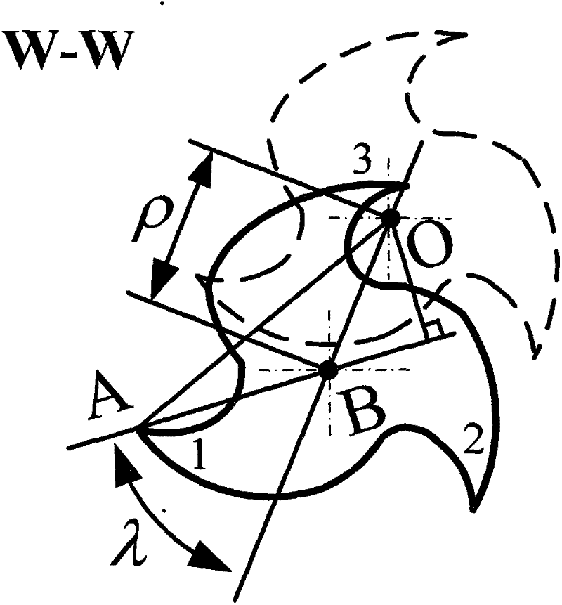
[0053] (3) At each axial position z j , to establish the deviation between tooth i and the axis of rotation of the machine tool spindle. Without loss of generality, according to the method in Document 3, for each axial position z j , first construct a set of deviations between the cutter teeth corresponding to the eccentric parameters ρ=8.31μm and λ=31.918° and the center of rotation of the machine tool spindle, and record the result as η i (z j ), as shown in the table below, j=1, 2,..., N, i=1, 2,..., N f . In order to be close to the actual test situation, when constructing η i (z j ),...

Embodiment 2

[0077] (1) Select the parameters of the end mill: the tool radius R is 8mm, the helix angle β is 30 degrees, and the number of tool teeth is N f is 3, assuming that the milling cutter is mounted on a three-axis vertical milling machine.

[0078] (2) Select N=1 tool axial position, and mark the coordinate of this axial position as z 1 =0.

[0079] (3) At the axial position z 1 , to establish the deviation between the cutter tooth i and the center of rotation of the machine tool spindle. Without loss of generality, according to the method in Document 3, first construct a set of deviations between the cutter teeth corresponding to the eccentric parameters ρ=8.31μm and λ=31.918° and the center of rotation of the machine tool spindle, and record the result as η i (z 1 ), as shown in the table below, i=1, 2, .., N f . In order to be close to the actual test situation, when constructing η i (z 1 ), a random error not exceeding 2.5 μm is added.

[0080]

[0081] (4) Accord...


PUM


Abstract

The invention discloses a method for calibrating radial eccentricity parameters in the milling process of a flat head end mill, which is used for solving the technical problems that in the prior art, the calibration of the radial eccentricity parameters in the milling process of the flat head end mill needs to be developed by relying on expensive testing equipment. The technical scheme is that asa dial indicator is adopted to test deviations between different cutter teeth and a rotating axis after the mill is clamped, a calibration model of the radial eccentricity parameters of the mill is established and the calibration of the radial eccentricity parameters is realized; as the dial indicator is adopted to test the deviations between different cutter teeth and the rotating axis after themill is clamped, the calibration model of the radial eccentricity parameters of the mill is established and the calibration of the radial eccentricity parameters is realized; and the method is simpleand reliable, and the constraint of relying on the expansive testing equipment is thrown off.

Description

technical field [0001] The invention relates to a method for calibrating tool eccentricity parameters in the milling process, in particular to a method for calibrating radial eccentricity parameters in the milling process of flat end mills. Background technique [0002] Document 1 "J.H.Ko, W.S.Yun, D.W.Cho, K.F.Ehmann, Development of a virtual machining system-Part 1: approximation of the size effect for cutting force prediction. International Journal of Machine Tools and Manufacture 42(2002) 1595-1605. "disclosed a method for calibrating the radial eccentricity parameters ρ and λ of flat end mills by using the measured instantaneous milling force. This method is based on the idea of ​​parameter research. The basic steps are: [0003] (1) Test the milling force by force measuring equipment; [0004] (2) Assume that the tool eccentricity parameters ρ=0 and λ=0; [0005] (3) According to the assumed eccentricity parameters, the technological geometric relationship between th...

Claims


Application Information

Patent Timeline
IPC IPC(8): B23Q17/09
Inventor 万敏张卫红杨昀王怡婷
Owner NORTHWESTERN POLYTECHNICAL UNIV
Why Eureka
Try Eureka