Mechanical arm for injection molding machine

A technology of manipulator and injection molding machine, applied in the field of manipulator, can solve the problems of unstable movement, low positioning accuracy, low safety performance, etc., and achieve the effect of improving safety and reliability, high positioning accuracy and improving stability

Active Publication Date: 2012-02-15
PERLMAN ELECTRICAL KUSN
View PDF8 Cites 36 Cited by
  • Summary
  • Abstract
  • Description
  • Claims
  • Application Information

AI Technical Summary

Problems solved by technology

[0003] However, at present, when overmolding semi-finished products, especially when overmolding iron products, it is often done manually, such as semi-finished iron parts Place it in the mold of the injection molding machine, and then take it out by manipulator or manual after overmolding. Therefore, the operation is automated or manual, and its work efficiency is low, the action is unstable, and the safety performance is low, which affects the quality of the product.
[0004]Moreover, the current injection molding machine uses a manipulator for metal product overmolding, because the traditional model is that the cylinder drives the magnet to move, that is, the product ejection mechanism uses the cylinder. And a magnet is installed on the cylinder push rod to inhale metal products. When unloading the product, shrink the cylinder push rod to the fixed position, and unload the product through the stop of the fixed plate. The inclination makes its positioning accuracy low, and the positioning pin needs to be fixed on the rear fixing plate. If there is no space, it needs to increase the fixing plate to place the positioning pin. Therefore, the structure of the manipulator is complicated, heavy, and the operation is unstable. Affect product quality and production efficiency

Method used


Image

  • Mechanical arm for injection molding machine
  • Mechanical arm for injection molding machine
  • Mechanical arm for injection molding machine

Examples


Embodiment

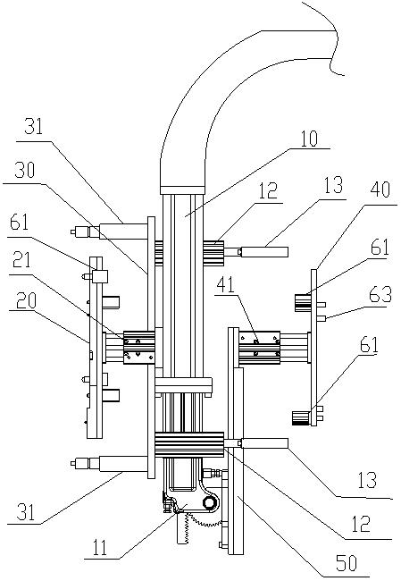
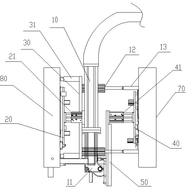
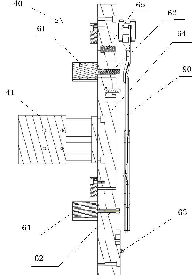
[0023] see Figure 1 to Figure 3 , the manipulator for the injection molding machine in this embodiment includes a connecting plate 10, a rotary motor 44 installed at the end of the connecting plate 41, a semi-finished grabbing plate 20 installed on one surface of the connecting plate 41 and another plate arranged on the connecting plate 10. The finished product grabbing plate 40 at the surface, the finished product grabbing plate 40 is connected with the rotating motor through a finished mechanical arm, and a second cylinder is installed on one end of the finished mechanical arm 50, which is connected with the finished product grabbing plate 40 through the second cylinder Connection, the other end of the finished mechanical arm 50 is connected with the connection plate 10 through the rotary motor 11 . The semi-finished grabbing plate 20 is fixed on the other surface of the connecting plate 10 through the mounting plate 30, and the first cylinder 21 connected with the semi-fin...


PUM


Abstract

The invention relates to a mechanical arm for an injection molding machine, comprising a connecting plate, a rotary motor arranged at the end of the connecting plate, a half-finished product grabbing plate arranged on one surface of the connecting plate, and a finished product grabbing plate arranged on the other surface of the connecting plate, wherein the finished product grabbing plate is connected with the rotary motor through a finished product mechanical arm, the half-finished product grabbing plate is fixed on the other surface of the connecting plate through a mounting plate, a first air cylinder connected with the half-finished product grabbing plate is arranged on the mounting plate, a second air cylinder is arranged on the finished product mechanical arm, and the finished product mechanical arm is connected with the finished product grabbing plate through the second air cylinder. According to the invention, by arranging the half-finished product grabbing plate and the finished product grabbing plate, the encapsulation and injection molding processes of products are completely operated by the mechanical arm substituted for manpower, thereby improving the production efficiency and operational stability, and preventing the products from being damaged, so that the invention has the advantages of high positioning accuracy, simplicity of operation, simple structure, safety and reliability.

Description

technical field [0001] The invention relates to a manipulator, in particular to a manipulator for an injection molding machine. Background technique [0002] With the development of computer and automation technology, manipulators are widely used in industrial production to replace manual operations. In the existing injection molding field, the role of the manipulator of the injection molding machine is to take out the injection molded product from the mold after injection molding. The action of the manipulator requires high precision, and the action must be stable and reliable. [0003] However, at present, when overmolding semi-finished products, especially when overmolding iron parts, it is often done manually, such as placing semi-finished iron parts in the mold of the injection molding machine, and then taking them out by manipulators after overmolding Or manually take out, therefore, operation is to do automation or manual operation, and its work efficiency is low, an...

Claims


Application Information

Patent Timeline
Patent Type & Authority Applications(China)
IPC IPC(8): B29C45/17B29C45/40B25J15/06
Inventor 向建伟
Owner PERLMAN ELECTRICAL KUSN
Why Eureka
Try Eureka