Method for measuring spot size of multi-element infrared ray shaft temperature detector

A measurement method and detector technology, applied in the direction of testing optical performance, etc., can solve the problems of poor operability, response signal attenuation, and inability to accurately judge the size of the spot, etc., to achieve rich information, improve measurement accuracy, and simple and fast measurement methods Effect

Inactive Publication Date: 2012-02-15
BEIJING CTROWELL INFRARED TECHN
View PDF4 Cites 8 Cited by
  • Summary
  • Abstract
  • Description
  • Claims
  • Application Information

AI Technical Summary

Problems solved by technology

The size of the baffle used for occlusion is fixed, which can only roughly estimate which round hole the spot size is similar to, but cannot accurately determine the size of the spot
Second, poor operability
When measuring, it is necessary to ensure that the center of the detector spot coincides with the center of the baffle, but the center of the spot is invisible, and it is difficult to ensure that the center coincides during measurement; and a slight deviation will cause a significant attenuation of the response signal, resulting in an error
Moreover, this method can only be used for unit detector spot measurement, and for multiple spot detectors, this method will be more difficult to test

Method used


Image

  • Method for measuring spot size of multi-element infrared ray shaft temperature detector
  • Method for measuring spot size of multi-element infrared ray shaft temperature detector
  • Method for measuring spot size of multi-element infrared ray shaft temperature detector

Examples


Embodiment Construction

[0026] The present invention will be further described in detail below in conjunction with the accompanying drawings.

[0027] A method for measuring the spot size of a multi-element infrared axial temperature detector proposed by the present invention specifically includes the following steps:

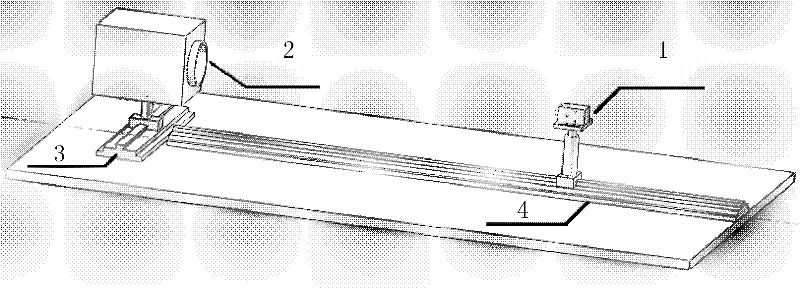
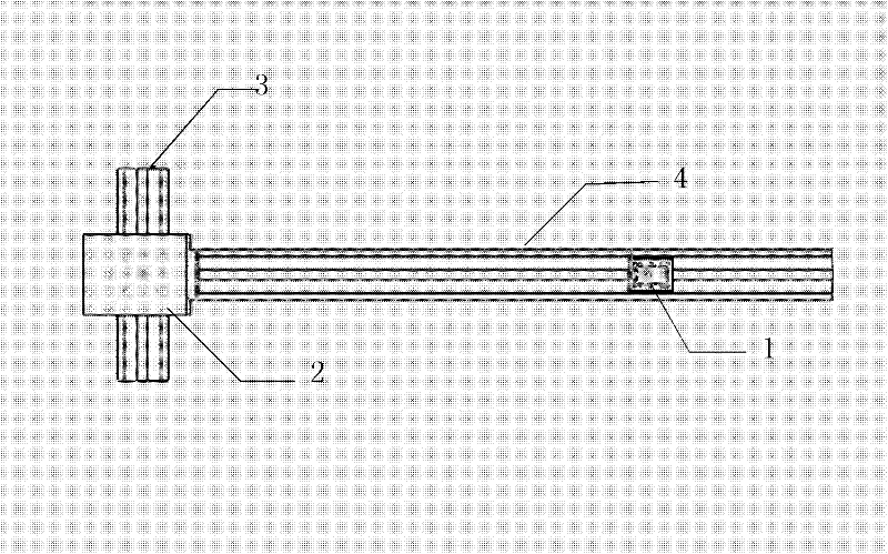
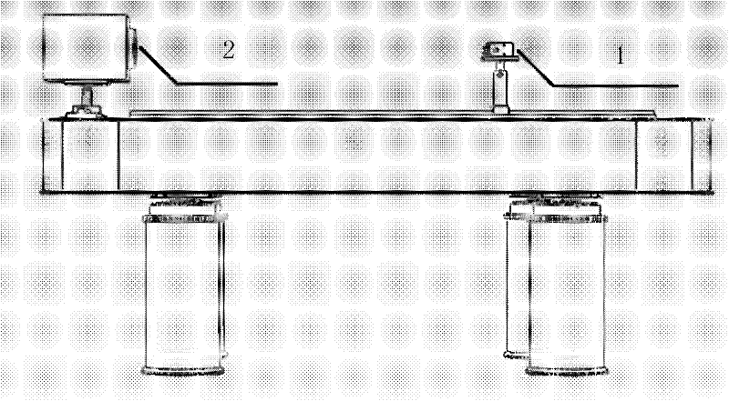
[0028] Step 1: Place the detector 1 on the B guide rail 4 of the T-shaped guide rail of the test platform, and adjust the direction of the detector 1 so that the normal line of the sensitive surface of the detector 1 is parallel to the B guide rail 4, and place the blackbody 2 on the A guide rail 3 The 0 scale position of the upper scale, the 0 scale is located on the side of the A guide rail 3, and the A guide rail 3 and the B guide rail 4 are kept vertical, such as Figure 1-A , 1-B and 1-C.

[0029] Step 2: Adjust the position of the detector 1 on the B guide rail 4, and set the detector 1 at a vertical distance of 50-100 cm from the A guide rail 3. At the same time, adjust the h...


PUM


Abstract

The invention provides a method for measuring a spot size of a multi-element infrared ray shaft temperature detector. The method comprises the following steps of: 1, arranging the detector and a black body on a T-shaped guide rail; 2, adjusting the central height of the detector and the black body; 3, starting the black body and the detector, and receiving a response signal; 4, continuously moving the black body, and recording a corresponding signal; 5, when the response signal is not generated, stopping moving the black body; 6, drawing the response signal and a corresponding black body position; and 7, acquiring the spot size. By the method for measuring the spot size of the multi-element infrared ray shaft temperature detector, the size of a spot can be accurately measured, and the measurement accuracy can at least reach the magnitude of 0.5cm and is obviously improved; and the measurement method is simple and quick, is rich in information amount and can be used for measuring the sizes of the spot of the detector in different directions.

Description

technical field [0001] The invention belongs to the technical field of detector optical performance testing, and relates to a method for measuring the spot size of a detector, in particular to a method for measuring the spot size of a multi-element infrared detector for train shaft temperature detection. Background technique [0002] The spot size refers to the area of ​​the infrared heat source that each infrared sensitive element in the infrared detector can actually feel; in the unit (only one sensitive element) detector, the spot size is the size of the field of view. [0003] At present, the detectors used for railway shaft temperature detection are mostly unit infrared detectors. For the test and measurement of the spot size of the detector, there are few accurate and quick measurement methods at present, and there are few related literature descriptions. When it is necessary to know the size information of the spot, the usual practice is: align the center of the dete...

Claims


Application Information

Patent Timeline
Patent Type & Authority Applications(China)
IPC IPC(8): G01M11/02
Inventor 王勇董烁毕方勇马丁熊伟
Owner BEIJING CTROWELL INFRARED TECHN
Why Eureka
Try Eureka