
Method for converting ladder diagram into PLC (Programmable Logic Controller) program command

A technology of program instructions and ladder diagrams, which is applied in the direction of electrical program control and sequence/logic controller program control, etc., can solve the problems of complex conversion program structure, limitation of conversion range, lack of optimization of results, etc., and achieve simplified conversion methods, The effect of saving search time and improving conversion speed

Inactive Publication Date: 2012-02-15
BEIJING UNION UNIVERSITY
View PDF4 Cites 16 Cited by
  • Summary
  • Abstract
  • Description
  • Claims
  • Application Information

AI Technical Summary

Problems solved by technology

[0003] However, the above method has the following disadvantages: 1. The conversion from the ladder diagram to the tree structure is relatively complicated, and must be completed with the help of auxiliary vertices, so that the generated results lack optimization.
2. The ladder diagram with complex topological connection structure cannot be converted, so the conversion range is limited
3. The structure of the tree-based conversion program is complex, and the calculation relationship between vertices and edges is more complicated during the conversion process. It is difficult to analyze the time complexity of the conversion process. Use on a large scale

Method used


Image

  • Method for converting ladder diagram into PLC (Programmable Logic Controller) program command
  • Method for converting ladder diagram into PLC (Programmable Logic Controller) program command
  • Method for converting ladder diagram into PLC (Programmable Logic Controller) program command

Examples


Embodiment Construction

[0026] The present invention will be described in detail below in conjunction with the accompanying drawings and embodiments.

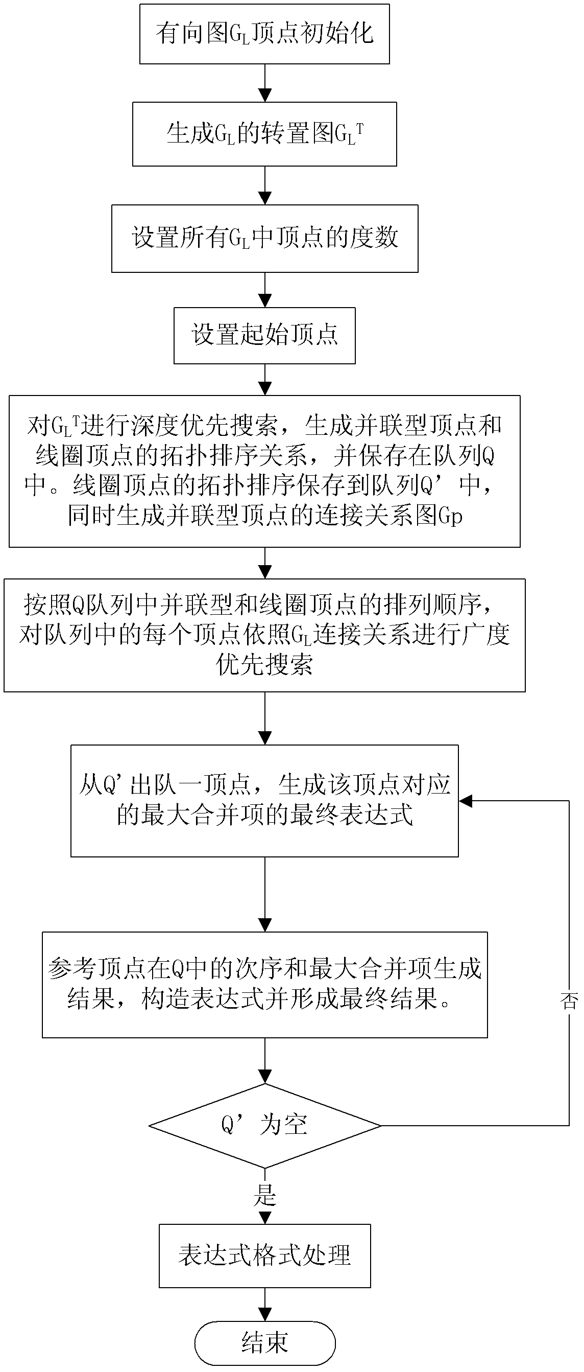
[0027] Such as figure 1 Shown, the present invention converts ladder diagram into the method for PLC program instruction and comprises the steps:

[0028] 1. Use the directed graph to represent the topology of the ladder diagram, and process the directed graph

[0029] 1) Initialize the vertices of the directed graph

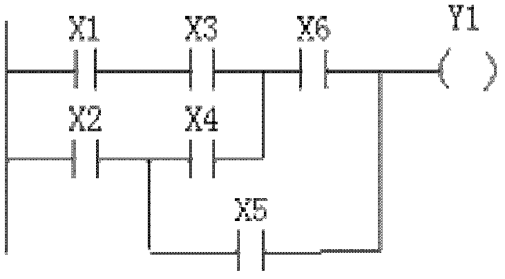
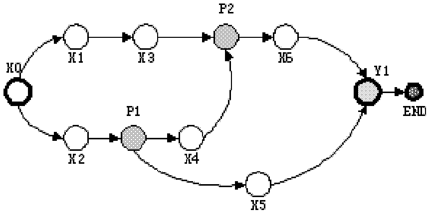
[0030] Such as Figure 2-9 As shown, the ladder diagram used by the PLC controller (such as figure 2 , Figure 4 , Figure 6 , Figure 8 shown) can be seen as a directed graph composed of different vertices corresponding to the ladder diagram (such as image 3 , Figure 5 , Figure 7 , Figure 9 ), the present invention utilizes G L Represents this directed graph.

[0031] Such as image 3 As shown, the directed graph G L The vertices in include the following types: start vertex X0, series vertices X1, X2, X3, X4, X5, X6,...


PUM


Abstract

The invention relates to a method for converting a ladder diagram into a PLC (Programmable Logic Controller) program command, which comprises the following steps of: 1, presenting a topological structure of a ladder diagram by using a directed graph; 2, traversing a transposed graph GL <T> by using a depth-first search method, storing a topological sorting relation of parallel-connection peaks and coil peaks in a queue Q; 3, carrying out breadth-first search on the parallel-connection peaks according to a connection relation of the directed graph GL, carrying out depth-first search on serial-connection peaks adjacently connected with the parallel-connection peaks, generating an AND expression of the directed graph GL on the whole serial-connection path and an OR expression of the serial-connection peaks; 4, generating a final expression of the maximum combining item of the parallel-connection peaks; 5, carrying out breadth-first search on a connection relation graph Gp by using the Q,figuring out an OR expression of the corresponding parallel-connection peaks and verifying, finally, constructing the maximum combining item into the AND expression to form a final result; 6, judgingwhether a queue Q' is empty; and 7, processing a starting peak. The invention can be widely applied to the process of converting the ladder diagram into the PLC program command.

Description

technical field [0001] The invention relates to a method for generating program instructions, in particular to a method for converting ladder diagrams into PLC program instructions. Background technique [0002] Programmable logic controller (Programmable Logic Controller, PLC) is the most commonly used general control equipment in the field of industrial control, and the ladder diagram is a necessary programming language for PLC. Although the ladder diagram is intuitive and easy to use, it cannot be run directly on the PLC. It is necessary to convert the ladder diagram into an instruction table to make the PLC control the controlled object according to the control logic of the ladder diagram. There are many ways to convert from ladder diagram to instruction list, but by far the better method is to convert the ladder diagram into a binary tree or some tree-like data structure, and then use some rules and some simple linear data structures, such as stacks Or queue, repeatedl...

Claims


Application Information

Patent Timeline
IPC IPC(8): G05B19/05
Inventor 王郁昕李红豫何宁
Owner BEIJING UNION UNIVERSITY
Learn More