Debugging device for flight test of unmanned aerial vehicle

A flight test and unmanned aerial vehicle technology, applied in electrical testing/monitoring, three-dimensional position/channel control, etc., can solve problems such as inability to store data, and achieve the effects of easy operation, simple structure, and shortened development cycle

Inactive Publication Date: 2012-02-15
CHANGCHUN INST OF OPTICS FINE MECHANICS & PHYSICS CHINESE ACAD OF SCI
View PDF5 Cites 19 Cited by
  • Summary
  • Abstract
  • Description
  • Claims
  • Application Information

AI Technical Summary

Problems solved by technology

[0005] In order to solve the problem of not being able to detect the change of the parameter in time to regulate the parameter and not being able to store the data, the present invention provides the following technical solutions to solve the above problem:

Method used


Image

  • Debugging device for flight test of unmanned aerial vehicle
  • Debugging device for flight test of unmanned aerial vehicle
  • Debugging device for flight test of unmanned aerial vehicle

Examples


Embodiment Construction

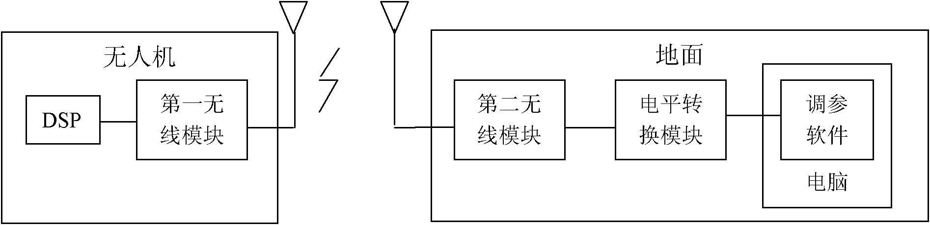
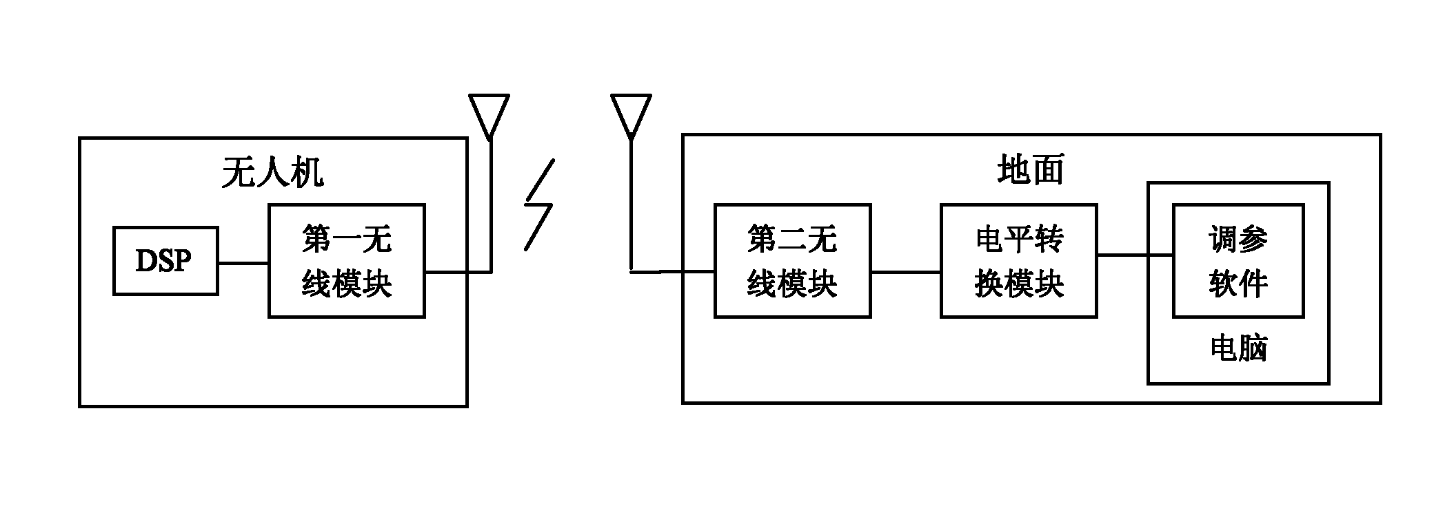
[0010] Such as figure 1 As shown, the debugging device of the present invention includes a DSP, a first wireless module, a second wireless module, a level conversion module and a computer assistant software module, wherein the DSP and the first wireless module are placed on the drone, and the second wireless module, The level conversion module and the computer assistant software module belong to the ground part. When the ground part needs to change the control parameters during the flight of the UAV, it can be changed in the assistant software of the computer. After level conversion, it reaches the second wireless module. After the first wireless module receives the data, it transmits it to the DSP through the serial port. , the number of parameters that can be changed in this way is large, and it saves trouble, saves time, and also reduces the weight of the simulator. The attitude and other information of the drone is sent from the DSP to the first wireless module. After rec...


PUM


Abstract

The invention discloses a debugging device for flight test of an unmanned aerial vehicle, relating to a debugging device and comprising an unmanned aerial vehicle part and a ground part, wherein the unmanned aerial vehicle part comprises a DSP (Digital Signal Processor) and a first wireless module, and the ground part comprises a second wireless module, a level switching module and a computer parameter adjusting software module; when changing the control parameter and motor rotating speed in the flight process of the unmanned aerial vehicle, the computer parameter adjusting software module sends a signal instruction which reaches to the second wireless module through the level switching module, and the second wireless module sends a wireless radio frequency signal which is sent to the DSP after being received by the first wireless module of the unmanned aerial vehicle part; the DSP changes the set of the received control parameter in the flight process of the unmanned aerial vehicle and then sends the changed control parameter to the first wireless module, and the first wireless module sends the wireless radio frequency signal, and the second wireless module receives the signal which is then switched to computer parameter adjusting software, thus, changed data can be displayed. The debugging device is simple in structure, high in reliability, easy to operate and capable of shortening the development period of an unmanned aerial vehicle control system.

Description

technical field [0001] The invention relates to a debugging device, in particular to a debugging device for unmanned aerial vehicle flight test. Background technique [0002] UAV is a powered, controllable, unmanned tactical UAV that can carry multiple mission loads, perform multiple tasks and can be reused. Due to its advantages of zero casualty risk and high mobility, it has attracted the Fang attaches great importance to it. The data transmission between the drone and the ground is divided into uplink and downlink, the uplink is from the ground to the drone, and the downlink is from the drone to the ground. [0003] Usually, when we debug the UAV, if we need to change the value of control parameters such as altitude, there are three ways as follows: 1. Use the remote control, but the number of channels of the remote control is limited, and you can also change the program continuously. To which part to adjust, map the used parameters to the corresponding remote control c...

Claims


Application Information

Patent Timeline
Patent Type & Authority Applications(China)
IPC IPC(8): G05B23/02G05D1/10
Inventor 张立华白越孙强续志军吴宏圣
Owner CHANGCHUN INST OF OPTICS FINE MECHANICS & PHYSICS CHINESE ACAD OF SCI
Why Eureka
Try Eureka