OLED (Optical Light Emitting Device) illuminating device and manufacture method thereof

A technology for lighting devices and transparent anodes, applied in the field of lighting, can solve problems such as uneven brightness and damage to OLED lighting devices, and achieve the effects of improving production yield and improving brightness unevenness.

Active Publication Date:
View PDF2 Cites 18 Cited by
  • Summary
  • Abstract
  • Description
  • Claims
  • Application Information

AI Technical Summary

Problems solved by technology

[0006] In order to solve the above technical problems, the purpose of the present invention is to provide an OLED lighting device and its manufacturing method, so as to reduce the probability of damage to the entire OLED lighting device due to short-circuit points on the premise of improving its brightness unevenness.

Method used


Image

  • OLED (Optical Light Emitting Device) illuminating device and manufacture method thereof
  • OLED (Optical Light Emitting Device) illuminating device and manufacture method thereof
  • OLED (Optical Light Emitting Device) illuminating device and manufacture method thereof

Examples


Embodiment 1

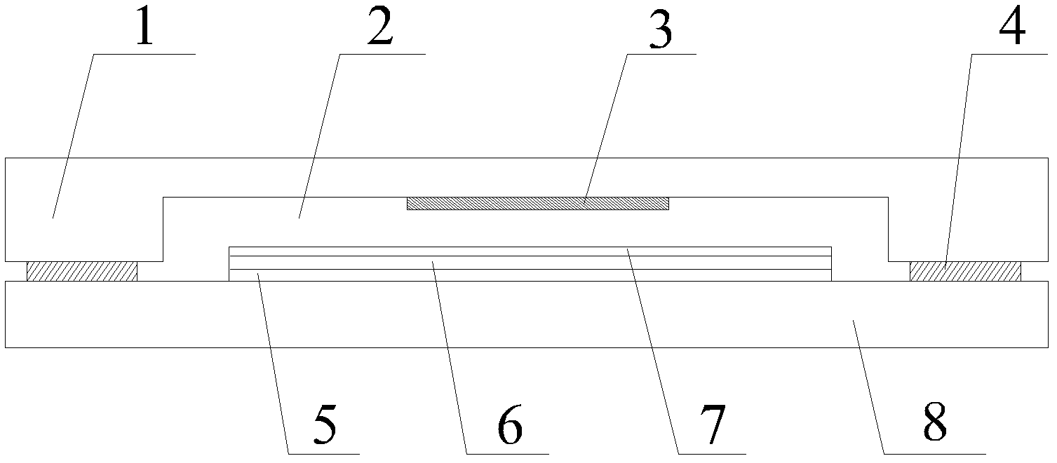
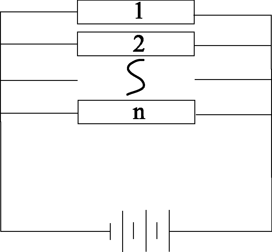
[0037] The OLED lighting device provided by the present invention comprises: an encapsulation back cover and a glass substrate arranged oppositely; a transparent anode, an organic functional layer and a metal cathode are sequentially arranged on the side of the glass substrate facing the encapsulation back cover. Wherein, the top view structural schematic diagram of the transparent anode is shown as Figure 4 As shown, the transparent anode includes: a plurality of mutually independent display unit electrodes (corresponding to light-emitting regions) 15 ; and an auxiliary metal electrode 16 connected to the plurality of mutually independent display unit electrodes 15 .

[0038] The shape of the display unit electrode 15 in the embodiment of the present invention is a square, and the shape of the display unit electrode in other embodiments may also be a triangle, a rectangle, a hexagon or other polygons. A channel electrode 17 is provided on four sides (or surroundings) of the ...

Embodiment 2

[0045] The OLED lighting device provided by the present invention has been described in detail above, and the manufacturing method of the OLED lighting device will be specifically introduced below.

[0046] refer to Figure 6 , Figure 6 It is a schematic flowchart of a method for manufacturing an OLED lighting device provided by an embodiment of the present invention, and the method specifically includes the following steps:

[0047] Step S1: providing a glass substrate.

[0048] Step S2: sequentially forming a transparent anode body layer and an auxiliary metal body layer on the glass substrate.

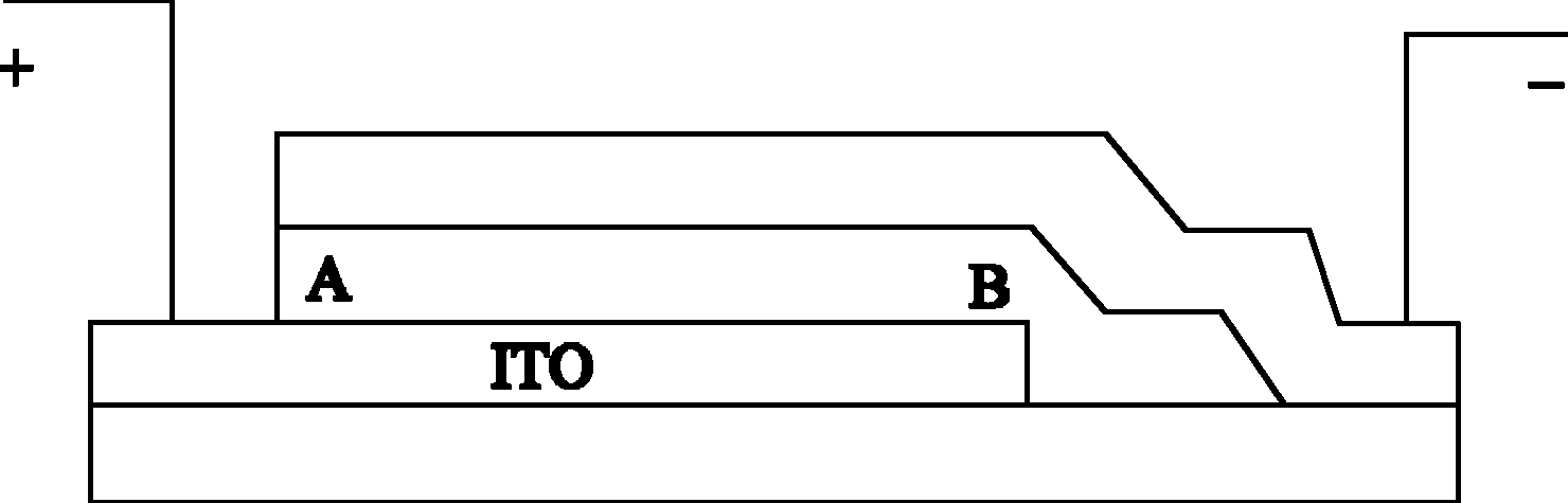
[0049] First, a transparent anode body layer is formed on one side of the glass substrate. The method for forming the transparent anode body layer may include evaporation, thermal spraying, magnetron sputtering or chemical vapor deposition, etc., and the transparent anode body layer is generally an ITO layer. . An auxiliary metal body layer is then formed on the transparent ano...


PUM


Abstract

The embodiment of the invention discloses an OLED (Optical Light Emitting Device) illuminating device and a manufacture method thereof. The OLED illuminating device comprises a glass substrate, and a transparent anode, an organic functional layer and a metal cathode which are sequentially arranged on the glass substrate, wherein the transparent anode comprises a plurality of display unit electrodes which are mutually independent from each other and auxiliary metal electrodes connected with the display unit electrodes which are mutually independent from each other. The OLED illuminating device provided by the embodiment of the invention not only can solve the problem that the brightness of light emitted by the device is nonuniform, but also can reduce the device damage probability for the occurrence of short circuit points.

Description

Technical field: [0001] The invention relates to the technical field of lighting, and more specifically, to an OLED lighting device and a manufacturing method thereof. Background technique: [0002] With the global energy crisis and people's increasing attention to environmental protection, energy conservation and environmental protection have become the mainstream of society. As far as the lighting industry is concerned, the development of green lighting with high efficiency, long life, safety, environmental protection and stable performance has become a common goal of all countries in the world. OLED (Organic Light-Emitting Diode, organic light-emitting diode) lighting devices have many advantages such as energy saving, carbon reduction, mercury-free, no ultraviolet rays, no high heat, no glare, thin and light, low driving voltage, solid-state lighting, surface light source, soft light, etc. , is being favored by many international lighting giants. [0003] Common OLED l...

Claims


Application Information

Patent Timeline
Patent Type & Authority Applications(China)
IPC IPC(8): H01L51/52H05B33/26
Inventor 柯贤军刘然苏君海何基强
Why Eureka
Try Eureka