Apparatus and method for electromechanical positioning
A mechanical, axial position technology, applied in the direction of generators/motors, metal processing machinery parts, piezoelectric effect/electrostrictive or magnetostrictive motors, etc., to achieve the effect of simple control
- Summary
- Abstract
- Description
- Claims
- Application Information
AI Technical Summary
Problems solved by technology
Method used
Image
Examples
no. 1 example ( pic 1)
[0060] figure 1The sectional view of the upper and lower axial positions shows only one friction mechanism of the two elastic friction mechanisms 15 . In fact, two stationary friction mechanisms are respectively provided at two axial positions. The two friction mechanisms at one axial position are still arranged uniformly in azimuth relative to the elastic friction mechanism 15a at the middle axial position, so as to play the role of guiding the cursor precisely in the axial direction. All five friction mechanisms are fastened at one axial position to the piezo element via a connecting element 13 and thus form a single friction mechanism group.
[0061] Elastic friction mechanism 15a is in figure 1 The middle axis is bonded in the middle of the coaxial fixed body 12 . The additional, non-movable static friction mechanism is connected indirectly via the coaxial fastening body 12 and via the disc 13 to the tubular piezoelectric element 11 . The friction mechanism consists of...
no. 2 example ( pic 2)
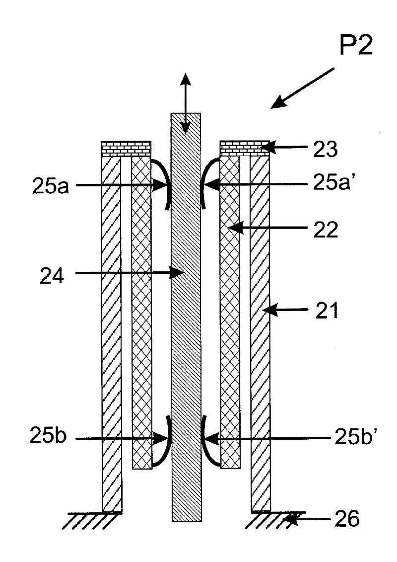
[0065] In embodiment 2 there are two elastic means 25a and 25a' at the upper axial position and two other elastic means 25b and 25b' at the lower axial position for exerting a normal force on the slider 24. These elastic means 25a and 25a' are formed by plug connections for the wires. This plug-in connection has elastic springs 25a, 25b and elastic semicircular friction surfaces 25a', 25b', and the vernier is pressed against the springs and friction surfaces by elastic force during operation.
[0066] The plug connectors 25a, 25a' are close to the disk 23 at the end and are connected to the piezoelectric element 21 via the disk. The connection bodies 25b, 25b' are fixed on the free ends of the tubular coaxial fixed body 22 and connected with the piezoelectric element 21 through the fixed body. All 4 friction mechanisms are fastened to the piezoelectric element at an axial position via connecting elements 23 and thus form a single friction mechanism group.
[0067] Said means...
Embodiment 3
[0079] Example 3 ( Figure 5 ):
[0080] Figure 5 The device P3 is shown at the top and the method according to the invention for operating the device is shown below.
[0081] P3 includes two piezoelectric elements 51a and 51b connected axially back and forth by a connecting member 53b.
[0082] The two piezo elements 51a and 51b of the arrangement are each provided at their outer, opposite ends with end discs as connection elements 53a and 53c. The tubular piezoelectric elements are also axially connected to each other by another disc 53b. One tubular piezoelectric element 51a is fixed at its free end to the base 56, while the opposite end of the second piezoelectric element is not fixed.
[0083] The cursor 54 is positioned axially along the double arrow. The vernier is fixed, guided and moved by three sets of friction mechanisms 55a, a', 55b, b' and 55c, c'. The friction mechanism group 55a and 55a' is formed by a plug connection and comprises two opposite elastic pa...
PUM
 Abstract
Description
Claims
Application Information
 - R&D
- Intellectual Property
- Life Sciences
- Materials
- Tech Scout
- Unparalleled Data Quality
- Higher Quality Content
- 60% Fewer Hallucinations
Browse by: Latest US Patents, China's latest patents, Technical Efficacy Thesaurus, Application Domain, Technology Topic, Popular Technical Reports.
© 2025 PatSnap. All rights reserved.Legal|Privacy policy|Modern Slavery Act Transparency Statement|Sitemap|About US| Contact US: help@patsnap.com


