Electric thermometer

An electronic thermometer and cavity technology, used in medical science, sensors, diagnostic recording/measurement, etc., can solve the problems of trouble, high cost, easy falling off and installation of metal contacts, etc. Effect

Inactive Publication Date: 2012-02-22
SHENZHEN H&T INTELLIGENT CONTROL
View PDF5 Cites 4 Cited by
  • Summary
  • Abstract
  • Description
  • Claims
  • Application Information

AI Technical Summary

Problems solved by technology

It aims to solve the problems of high cost, easy falling off of metal contacts and troublesome installation of the existing electronic thermometer structure due to the bonding of the metal contacts and the shell by glue

Method used


Image

  • Electric thermometer
  • Electric thermometer
  • Electric thermometer

Examples


Embodiment Construction

[0021] In order to make the object, technical solution and advantages of the present invention clearer, the present invention will be further described in detail below in conjunction with the accompanying drawings and embodiments. It should be understood that the specific embodiments described here are only used to explain the present invention, not to limit the present invention.

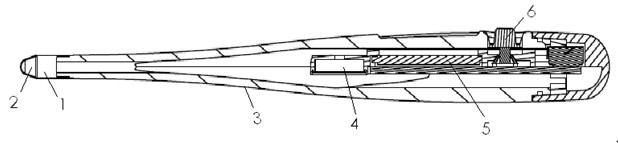
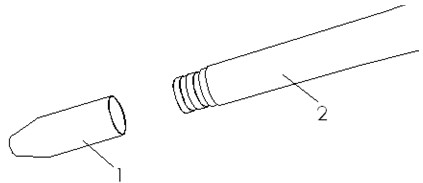
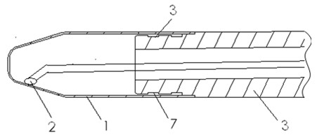
[0022] Such as Figure 4 with Figure 5 as shown, Figure 4 A cross-sectional view of the structure of the electronic thermometer provided by the present invention, Figure 5 The schematic structural diagram of the electronic thermometer provided by the present invention only shows the parts related to this embodiment for the convenience of description. Such as Figure 4 with Figure 5 As shown, the electronic thermometer disclosed in the present invention includes a temperature sensing sensor 4, a housing 1, a printed circuit board 5, a display device 2 and a touch switch 3, and the printed c...


PUM


Abstract

The invention is applicable to the technical field of body temperature measurement, and in particular relates to an electric thermometer. The electric thermometer comprises a temperature induction sensor, a shell, a printed circuit board (PCB), a display device and a touch switch, wherein, the PCB is arranged in a cavity enclosed by the shell; the display device is fixedly arranged on the shell and is electrically connected with the PCB; the touch switch is arranged on the shell and is electrically connected with the PCB; the shell is of an integral structure; and the temperature induction sensor is tightly attached to the surface of the inner wall of the cavity enclosed by the shell and is electrically connected with the PCB. The electric thermometer has the advantages of simple structure, low cost and strong practicability, and is safe and convenient to use.

Description

technical field [0001] The invention belongs to the technical field of body temperature measurement, in particular to an electronic thermometer. Background technique [0002] With the development of modern doctor technology, higher requirements are put forward for the measurement of body temperature. Usually, mercury thermometers and electronic thermometers are used to measure body temperature. Because electronic thermometers are easy to use and intuitive to display, they are more and more widely used. Such as figure 1 , figure 2 with image 3 As shown, the electronic thermometers currently on the market at least include a metal sensing head 1 , a temperature sensitive resistor 2 , a plastic casing 3 , a display device 4 , a printed circuit board 5 , and buttons 6 . Usually, the metal sensing head 1 is glued together with the plastic casing 3 by glue 7 . The temperature sensitive resistor 2 is arranged in the metal induction head 1 . The working process of the current ...

Claims


Application Information

Patent Timeline
Patent Type & Authority Applications(China)
IPC IPC(8): A61B5/01
Inventor 刘鑫
Owner SHENZHEN H&T INTELLIGENT CONTROL
Why Eureka
Try Eureka