Sling for hoisting thread steel

A threaded steel and spreader technology, applied in the field of spreaders, can solve the problems of small contact area between the suction cup and the threaded steel, easy wear of the wire rope, production accidents, etc., to reduce the probability of accidents, not easy to wear and tear, easy to operate and The effect of production

Inactive Publication Date: 2012-02-22
HEILONGJIANG JIANLONG IRON & STEEL
View PDF0 Cites 6 Cited by
  • Summary
  • Abstract
  • Description
  • Claims
  • Application Information

AI Technical Summary

Problems solved by technology

[0003] The present invention solves the problem that the small contact area between the sucker of the magnetic disk crane and the threaded steel causes it to fall easily during the hoisting process, and the friction between the steel wire rope and the threaded steel of the wire rope lockset is relatively large, which causes the steel wire rope to be easily worn or even broken, thereby causing production accidents, and further proposes A hanger for hoisting threaded steel

Method used


Image

  • Sling for hoisting thread steel
  • Sling for hoisting thread steel
  • Sling for hoisting thread steel

Examples


specific Embodiment approach 1

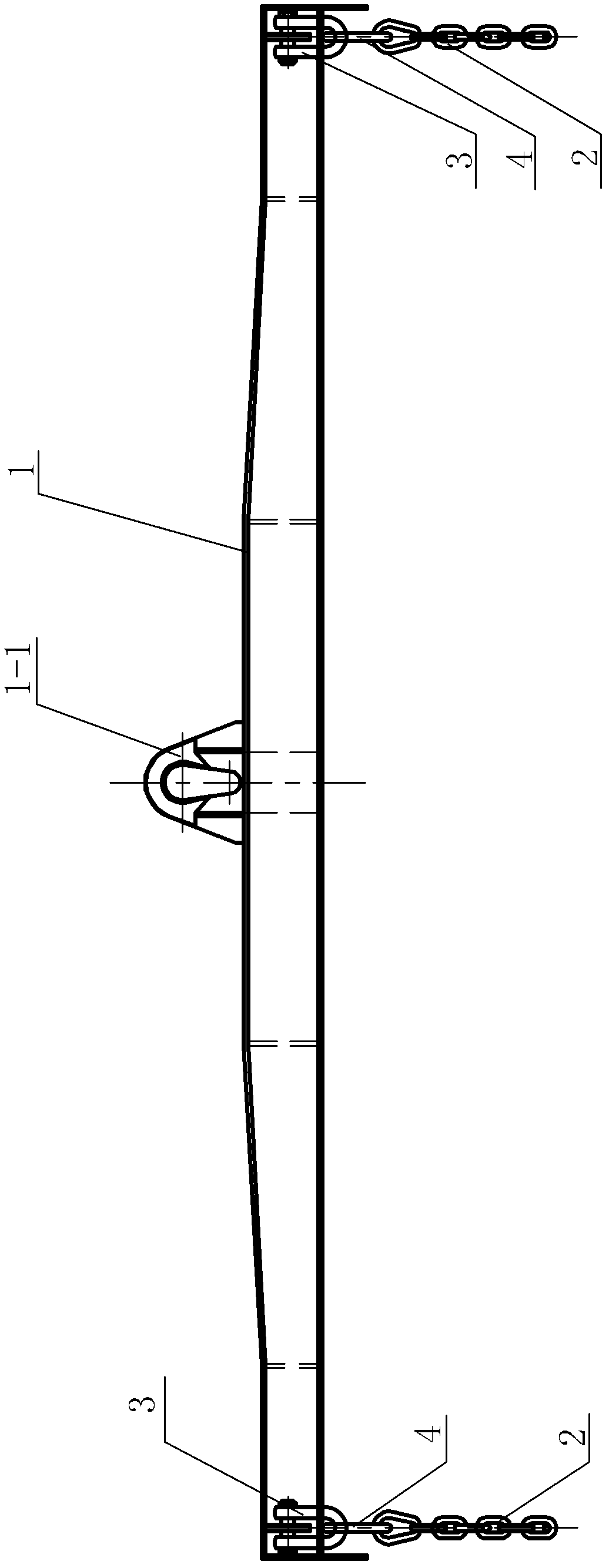
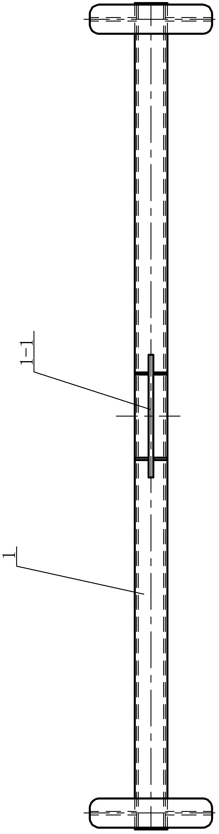
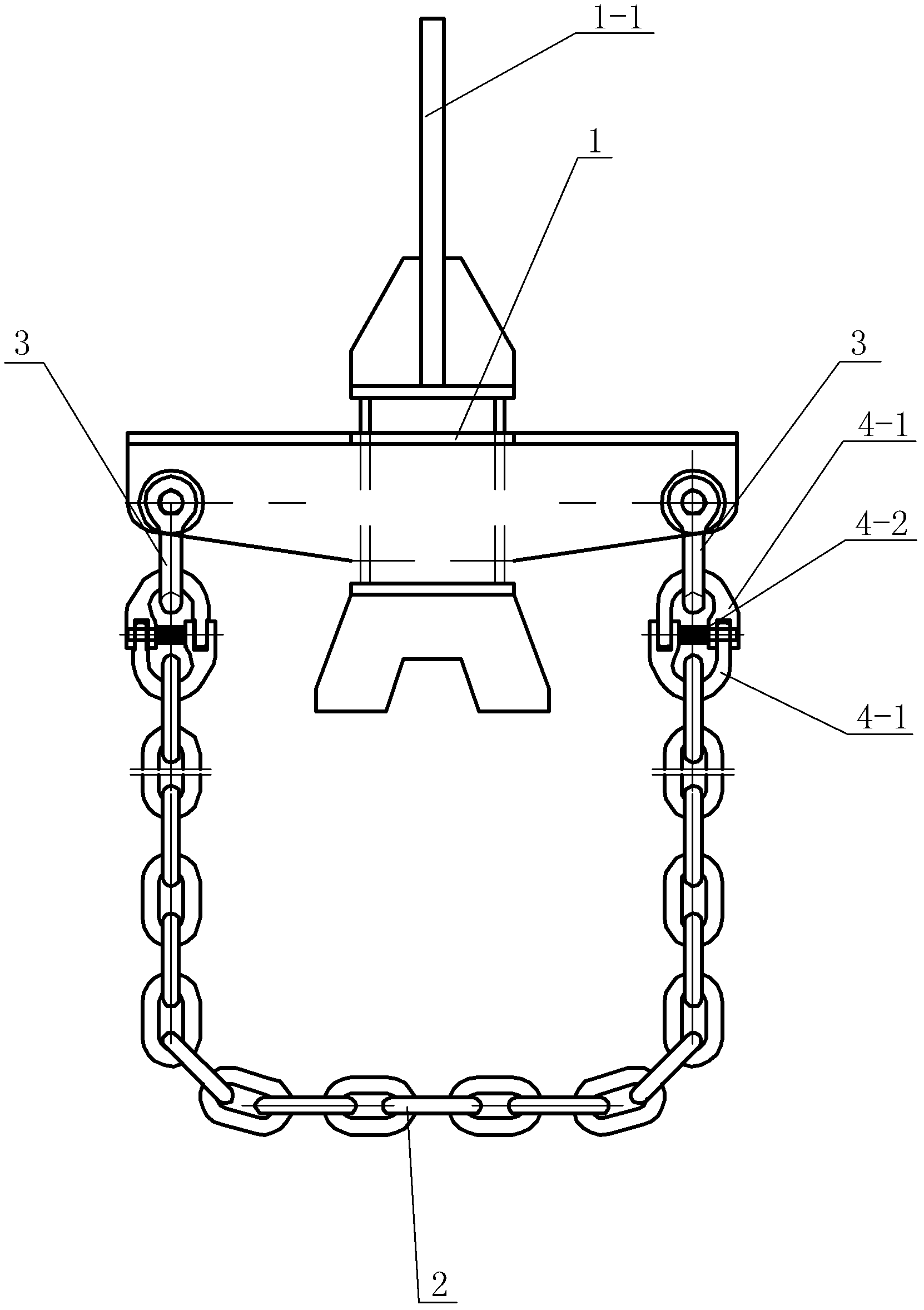
[0007] Specific implementation mode one: combine figure 1 , figure 2 with image 3 Describe this embodiment mode, the suspender of a kind of hoisting threaded steel described in this embodiment mode comprises beam 1, two chains 2 and four U-shaped rings 3, and the lower surface of described beam 1 two ends is respectively provided with two U-rings parallel to each other. The two ends of each chain 2 are respectively connected with a U-shaped ring 3 , and the two ends of each chain 2 are located at the same end of the beam 1 . In this embodiment, the chain 2 is used to hoist the finished threaded steel product. During the hoisting process, the friction between the chain 2 and the finished threaded steel product is small. chance of accidents.

specific Embodiment approach 2

[0008] Specific implementation mode two: combination image 3 Describe this embodiment, the two locks of each lock chain 2 of the suspender described in this embodiment are respectively provided with a lock assembly 4, and each lock assembly 4 includes two U-shaped lock rings 4- 1 and the pin shaft 4-2, the open ends of the two U-shaped lock rings 4-1 are plugged together through the pin shaft 4-2, and the two U-shaped lock rings 4-1 form a closed oval lock. Other components and connections are the same as those in the first embodiment.

specific Embodiment approach 3

[0009] Specific implementation mode three: combination figure 1 , figure 2 with image 3 To illustrate this embodiment, a hanger 1-1 is provided in the middle of the upper surface of the crossbeam 1 of a hanger for hoisting rebar in this embodiment. Other components and connections are the same as those in the first embodiment.

[0010] working principle

[0011] When the present invention is in use, the two ends of the finished threaded steel are suspended by a chain 2 respectively, the connecting hanger 1-1 on the crossbeam 1 is connected with the hook of the crane, and then the threaded steel is hoisted flatly to a designated position to complete the hoisting work.


PUM


Abstract

Relating to a sling, the invention specifically relates to a sling for hoisting thread steel. The invention aims to provide a solution to the problems that a small contact area between a sucker of a disk suspension and thread steel results in easy falling during hoisting, and great fraction force between a wire rope of a wire rope lockset and the thread steel leads to easy abrasion and even break of the wire rope and thereby causes production accidents. The sling of the invention comprises a beam 1, two chains 2, and four U-shaped rings 3. Specifically, lower surfaces at two ends of the beam 1 are respectively provided with two U-shaped rings 3 in parallel, two ends of each chain 2 are respectively connected to a U-shaped ring 3, and two ends of each chain 2 are located at one end of the beam 1. The sling provided in the invention is used for hoisting thread steel finished products.

Description

technical field [0001] The invention relates to a sling, in particular to a sling for hoisting threaded steel. Background technique [0002] The hoisting of rebar finished products is currently generally carried out by disk hoisting and wire rope locks. Since the rebar finished products are bundled and transported, the contact area between the disk hoisting suction cup and the rebar is small, resulting in low safety factor and easy fall during hoisting. Wire rope locks In the process of hoisting the finished rebar, the friction between the wire rope and the rebar is relatively large, which makes the wire rope easy to wear or even break, which causes safety hazards and increases the cost of use. Contents of the invention [0003] The present invention solves the problem that the small contact area between the sucker of the magnetic disk crane and the threaded steel causes it to fall easily during the hoisting process, and the friction between the steel wire rope and the thr...

Claims


Application Information

Patent Timeline
Patent Type & Authority Applications(China)
IPC IPC(8): B66C1/12
Inventor 翟长宏戴诗浩赵永明
Owner HEILONGJIANG JIANLONG IRON & STEEL
Why Eureka
Try Eureka