
Spinning assembly and spinning part

A spinning assembly and spinning technology, applied in the field of raw material supply, can solve the problems of aggravating the clogging of the spinneret, wasting the polymer solution, and taking a long time, so as to eliminate the coagulation of the solution and the increase of impurities, save working time, and reduce maintenance. Simple to use effects

Active Publication Date: 2012-02-22
HANGZHOU BANGLIAN SPANDEX
View PDF12 Cites 19 Cited by
  • Summary
  • Abstract
  • Description
  • Claims
  • Application Information

AI Technical Summary

Problems solved by technology

Cleaning a large number of metal hoses with different bending degrees and lengths requires a lot of work, which also affects production efficiency
In addition, part of the solidified particles will also become impurities in the polyurethane solution, which will aggravate the clogging of the spinneret
[0007] In addition, each metal hose needs to be removed when cleaning the spinneret, which takes a long time, and a lot of polymer solution is wasted in order to eliminate the gas entering the metering device due to the replacement of the spinneret

Method used

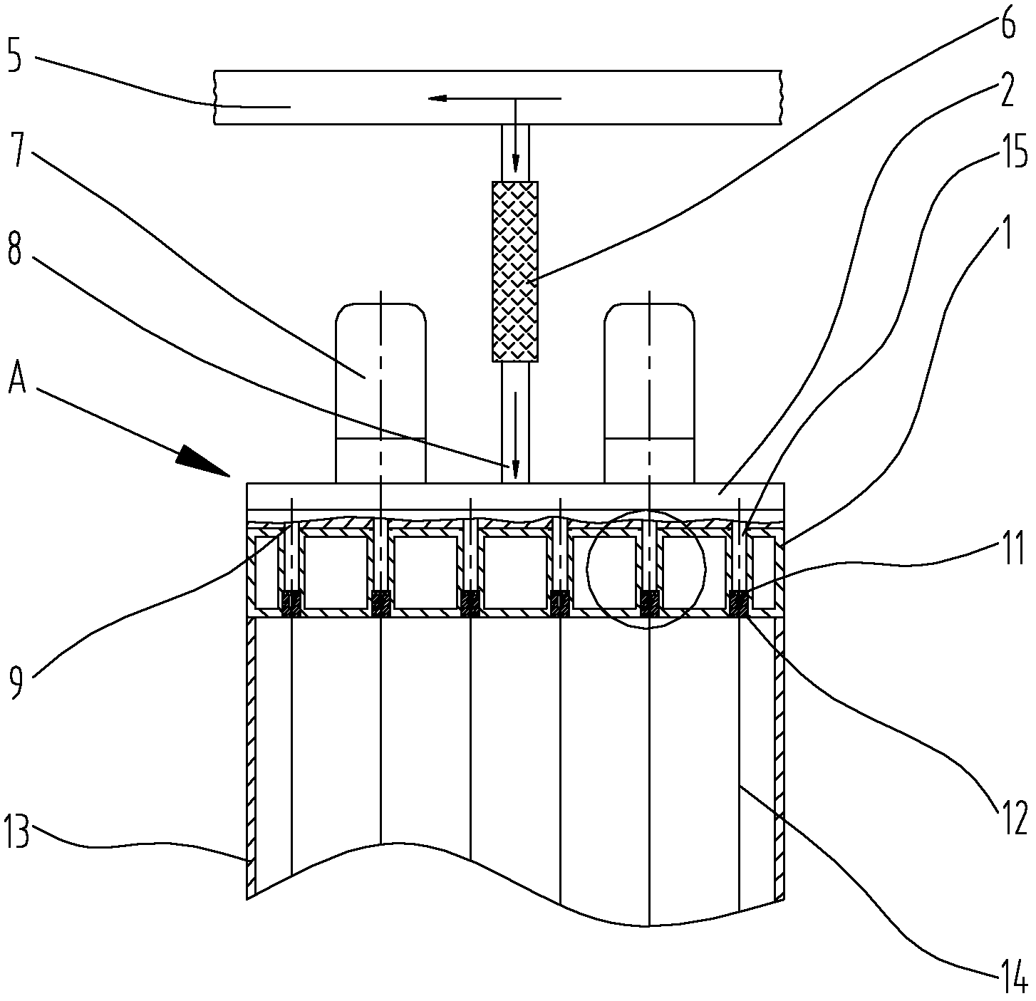
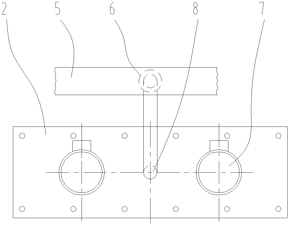
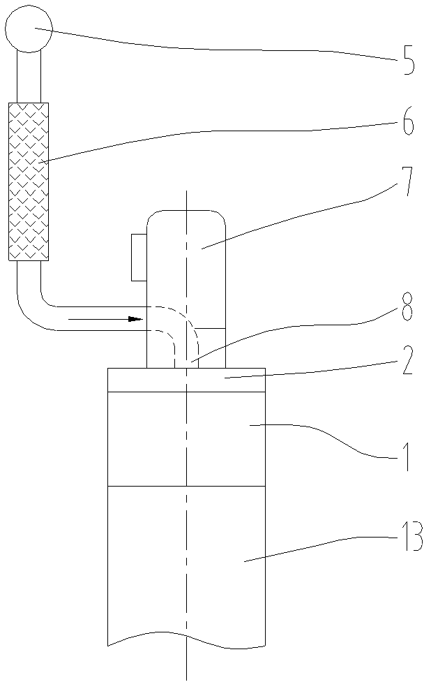

Image

  • Spinning assembly and spinning part
  • Spinning assembly and spinning part
  • Spinning assembly and spinning part

Examples


Embodiment Construction

[0049] The examples described here are specific specific implementations of the present invention, and are used to illustrate the concept of the present invention. They are all explanatory and exemplary, and should not be construed as limiting the implementation of the present invention and the scope of the present invention. In addition to the embodiments described here, those skilled in the art can also adopt other obvious technical solutions based on the claims of the application and the contents disclosed in the description, and these technical solutions include adopting any obvious changes made to the embodiments described here. Replacement and modified technical solutions. The scope of the technical solutions claimed in the present invention is defined by the claims of the present application.

[0050] The accompanying drawings in this specification are schematic diagrams, which assist in explaining the concept of the present invention, and schematically and schematicall...


PUM


Abstract

The invention discloses a spinning assembly and a spinning part. The spinning assembly is used for producing polyurethane fibers and comprises a metering device and the spinning part, wherein the metering device is provided with one inlet and a plurality of outlets, the inlet is connected with a filtering and pressure stabilizing device, the outlets are directly connected with the spinning part, the spinning part is a box body with a cavity, the box body is internally provided with holes of different numbers, the number of the holes corresponds to the number of the polyurethane fibers in each spinning station, a filter and a spinneret are arranged inside each hole, the outlets of the metering device are correspondingly connected onto the holes of the spinning part, and the centers of the outlets of the metering device and the centers of the holes of the spinning part are homocentric. According to the invention, the production quality of the polyurethane fibers can be increased, the production efficiency can be increased, and the spinning assembly and the spinning part are simple and rapid to install and maintain.

Description

technical field [0001] The invention relates to an equipment and a method for realizing raw material supply in polyurethane dry solution spinning by metering, distributing and forming multi-beam solution flows of polyurethane chemical solution. Background technique [0002] In the polyurethane fiber dry production process, chemical raw materials are polymerized to form a polymer solution, and the polymer solution is transported to the metering device of each spinning station through pipelines, and the metering device forms multiple streams of solution through metering and distribution. [0003] Figure 6-8 The structure of a prior art device is shown. In existing equipment, the polymer solution is transported to the metering device through pipelines. The metering device generally has one inlet and multiple outlets. In the metering device, the polymer solution is distributed into multiple smaller solution streams. The solution flow is connected to the spinning part through a...

Claims


Application Information

Patent Timeline
IPC IPC(8): D01D13/00D01D5/04D01D4/02D01D4/06D01D4/08
Inventor 袁祖涛张剑波李勇张运启
Owner HANGZHOU BANGLIAN SPANDEX
Learn More